
Multi-touch input actual-size display screen for scanned items

Active Publication Date: 2011-02-24
XEROX CORP
View PDF19 Cites 18 Cited by
  • Summary
  • Abstract
  • Description
  • Claims
  • Application Information

AI Technical Summary

Benefits of technology

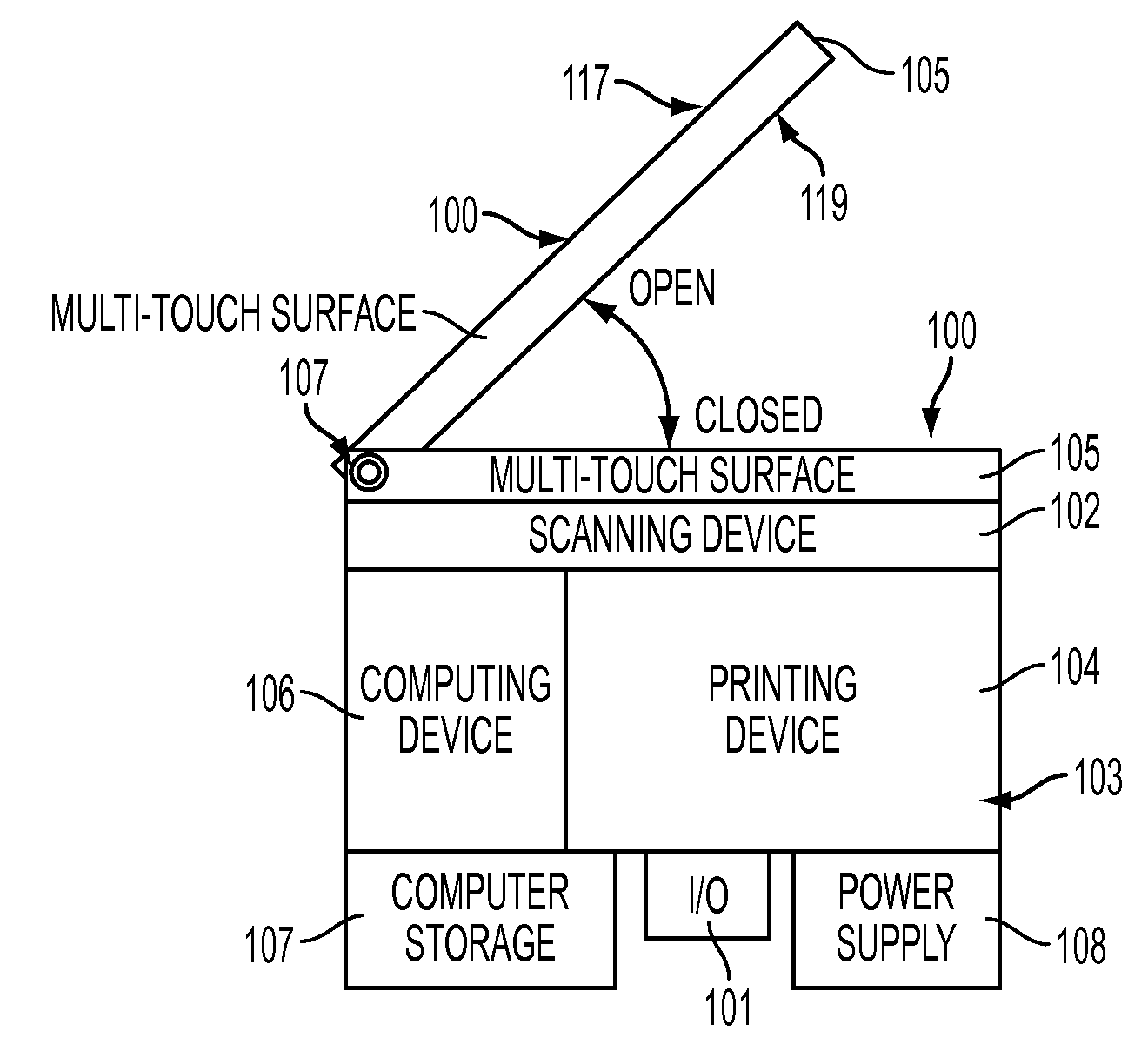
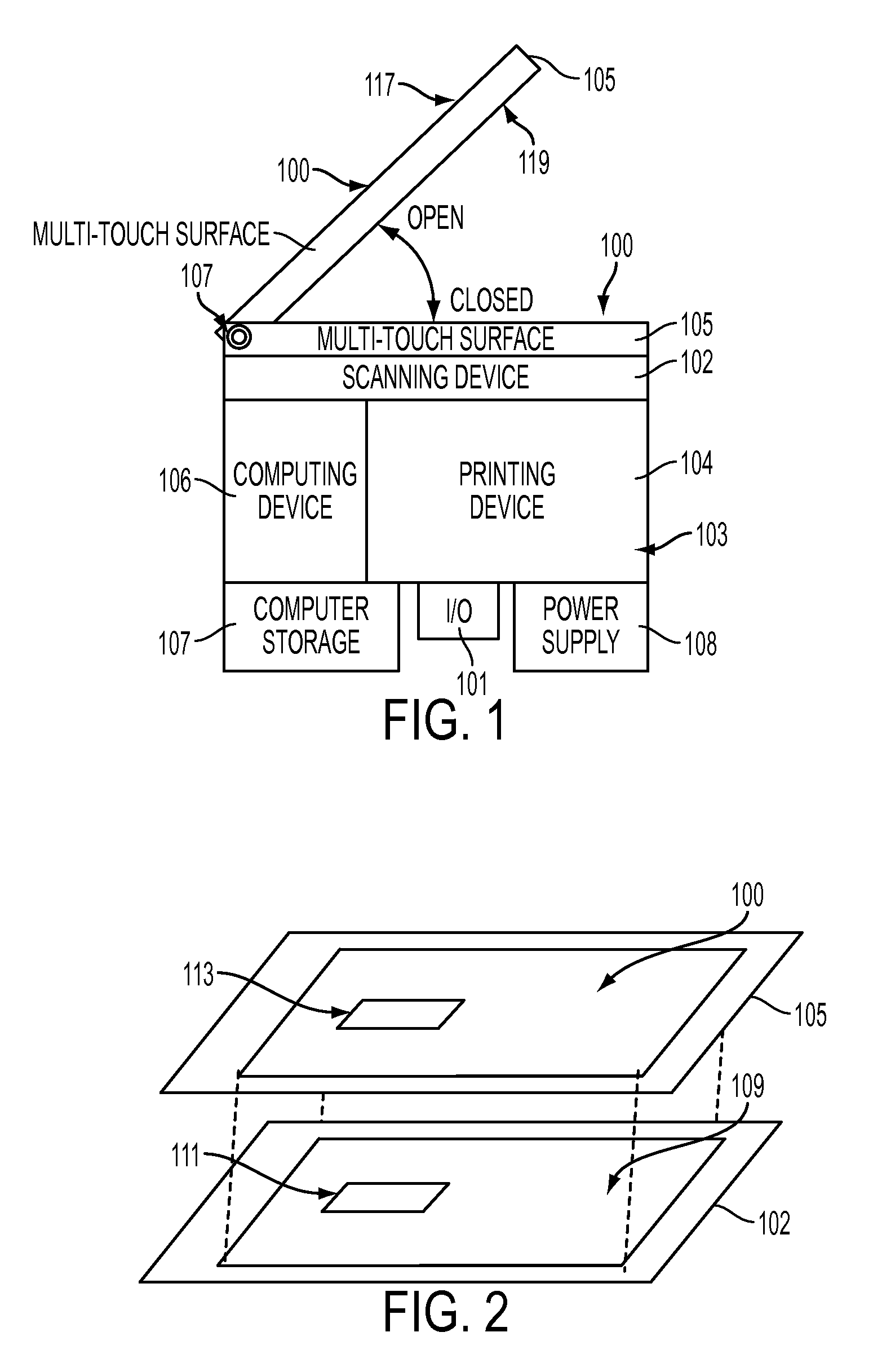
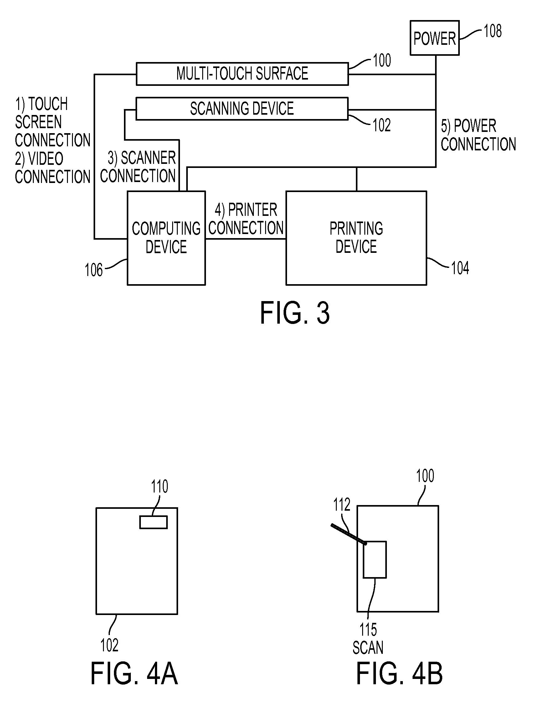
[0004]With embodiments herein, a scanner is operatively connected to the processor, as is a touch screen graphic user interface. The scanner is positioned to scan a predetermined “scan area.” The touch screen has a screen area that has dimensions corresponding to the scan area. In other words, the touch screen is the same size (or approximately the same size) as the scan area and, therefore, the touch screen displays scanned items in actual size (or approximately actual size). This allows the user to feel as though they are working with and manipulating the actual item that was scanned.
[0005]The touch screen is positioned adjacent the scan area such that the scan area is aligned with the screen area. By being “aligned with” the scan area, the touch screen can be directly on top of a platen where the scanned item was placed. Alternatively, the touch screen can be “aligned with” a fixed-position scanner by being directly below the location where the fixed-position scanner is located. In embodiments herein, the location of the scanner is maintained proximate to and aligned with the touch screen to provide the same appearance of the scanned item on the screen (same size and location of the physical scanned item) to increase the intuitive nature of the experience provided by the embodiments herein.

Problems solved by technology

Graphic user interfaces that accompany conventional scanners, copiers, multi-function printing machines, etc., do not reflect the scanned item in an accurate and realistic manner that the user can interpret and manipulate easily.
Current touch interfaces used with scanners, copiers, multi-function printing machines, etc., allow for only one touch as a time, which limits the ability of the user to manipulate the items.
With such conventional devices, touch screens only allow users to set the number of copies, change the size, set the duplex, and rotate the document; however, users cannot see the actual results of their manipulations until the document is actually printed.

Method used


Image

  • Multi-touch input actual-size display screen for scanned items
  • Multi-touch input actual-size display screen for scanned items
  • Multi-touch input actual-size display screen for scanned items

Examples


Embodiment Construction

[0033]As mentioned above, current user interfaces of copiers do not reflect the actual input and output in a manner that the user can see or change easily. Current touch interfaces used with scanners, copiers, multi-function printing machines, etc., allow for only one touch as a time which limits the ability to send manipulations into the copier. Documents that are printed from a copier need user input to set the number of copies, change the size, set the duplex, and rotate the document; however, users cannot see the results of their inputs until they print the document.

[0034]The embodiments herein can, for example, include a multi-touch screen, software, a document scanning device, a printing device, etc. A multi-touch screen is an input / output device that allows for one or more simultaneous inputs (where the surface is simultaneously touched in multiple locations). Touch screens generally include a display surface (such as a liquid crystal display or similar display) and a surface...


PUM


Abstract

An apparatus comprises a processor, a scanner operatively connected to the processor, and a touch screen graphic user interface operatively connected to the processor. The scanner is positioned to scan a predetermined scan area and the touch screen has a screen area that has dimensions corresponding to the scan area. The touch screen is positioned adjacent the scan area such that the scan area is aligned with the screen area.

Description

BACKGROUND AND SUMMARY[0001]Embodiments herein generally relate to scanning devices such as electrostatographic printers and copiers or reproduction machines, and more particularly, concern a scanning device having a multi-touch graphic user interface screen that displays scanned items at their actual size.[0002]Graphic user interfaces that accompany conventional scanners, copiers, multi-function printing machines, etc., do not reflect the scanned item in an accurate and realistic manner that the user can interpret and manipulate easily. Current touch interfaces used with scanners, copiers, multi-function printing machines, etc., allow for only one touch as a time, which limits the ability of the user to manipulate the items. With such conventional devices, touch screens only allow users to set the number of copies, change the size, set the duplex, and rotate the document; however, users cannot see the actual results of their manipulations until the document is actually printed.[000...

Claims


Application Information

Patent Timeline
IPC IPC(8): G06F3/041
CPCG06F3/0482G06F3/04845G06F3/0485G06F3/04883G06F2203/04807H04N2201/0094H04N1/00411H04N1/00493H04N1/00551H04N2201/0081H04N2201/0091H04N1/00408
Inventor KUMOR, DAMIAN
Owner XEROX CORP
Learn More