
Signal acquisition monitoring system

A monitoring system and signal acquisition technology, applied in the direction of signal transmission system, closed-circuit television system, TV system components, etc., can solve the problems of inconvenient observation and analysis, no, lack of intuition, etc., to improve intuition and reduce costs , save the effect of the line

Inactive Publication Date: 2013-08-28
WUXI INST OF COMMERCE
View PDF4 Cites 0 Cited by
  • Summary
  • Abstract
  • Description
  • Claims
  • Application Information

AI Technical Summary

Problems solved by technology

[0002] Signal acquisition is the most common work process. For example, in various industries such as machinery, electronics, petroleum, and chemical industry, as well as many aspects of people's daily life, the operation of signal acquisition will be involved. The result of signal acquisition will directly affect Various related operations in the future, so in all aspects, signal acquisition is a very important step, so people will monitor the signal acquisition process and results, the monitoring of the acquisition process such as recording the acquisition point through the camera, the actual acquisition equipment The monitoring of the collection results is to directly upload the collected data signals to the monitoring terminal, and the monitoring terminal directly obtains and analyzes them; there are two kinds of signals involved here, one is the data signal, and the other is the video signal , the existing signal acquisition and monitoring system usually monitors the two signals separately, that is, the two signal output devices are used to output the data signal and the video signal respectively. It is not an economical thing, and the separation of video signal and data signal is not convenient for staff to observe and analyze, and lacks intuitive sense

Method used


Image

  • Signal acquisition monitoring system

Examples


Embodiment Construction

[0014] The specific implementation manners of the present invention will be further described in detail below in conjunction with the accompanying drawings.

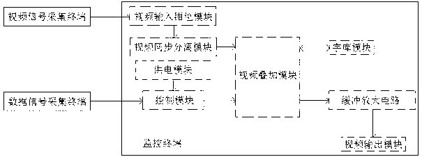
[0015] Such as figure 1 As shown, the present invention designs a signal acquisition and monitoring system, including a monitoring terminal, and a data signal acquisition terminal and a video signal acquisition terminal that communicate with the monitoring terminal respectively; wherein, the monitoring terminal includes a power supply module, an information output module and a control module, The power supply module is connected with the control module to supply power to each module in the monitoring terminal; the monitoring terminal is respectively connected with the data signal acquisition terminal and the video signal acquisition terminal for communication; the monitoring terminal also includes a video synchronization separation module, a video superimposition module and a font module , the information output module i...


PUM


Abstract

The invention relates to a signal acquisition monitoring system. The signal acquisition monitoring system comprises a monitor terminal, a data signal acquisition terminal and a video signal acquisition terminal, wherein the data signal acquisition terminal and the video signal acquisition terminal are respectively in communication with the monitor terminal. The monitor terminal comprises a power module, an information output module, a control module, a video synchronization separation module, a video overlap module and a word stock module. The information output module is a video output module. The video overlap module is connected with the video synchronization separation module, the word stock module, the control module and the video output module respectively. The data signal acquisition terminal is in connection and communication with the control module. The video signal acquisition terminal is in connection and communication with the video synchronization separation module. According to the signal acquisition monitoring system, the effect that data signals and video signals share the same picture can be achieved, the visuality for observing signals of the monitor terminal is effectively improved, working efficiency is improved, cost is lowered, and space is saved.

Description

technical field [0001] The invention relates to a signal acquisition and monitoring system. Background technique [0002] Signal acquisition is the most common work process. For example, in various industries such as machinery, electronics, petroleum, and chemical industry, as well as many aspects of people's daily life, the operation of signal acquisition will be involved. The result of signal acquisition will directly affect Various related operations in the future, so in all aspects, signal acquisition is a very important step, so people will monitor the signal acquisition process and results, the monitoring of the acquisition process such as recording the acquisition point through the camera, the actual acquisition equipment The monitoring of the collection results is to directly upload the collected data signals to the monitoring terminal, and the monitoring terminal directly obtains and analyzes them; there are two kinds of signals involved here, one is the data signal...

Claims


Application Information

Patent Timeline
Patent Type & Authority Applications(China)
IPC IPC(8): H04N7/18G08C17/02H04N5/265H04N5/44
Inventor 戴明孟召议
Owner WUXI INST OF COMMERCE
Learn More