Field terminable optical fiber connector with splice element

a technology of splice element and optical fiber connector, which is applied in the field of optical fiber connector, can solve the problems of incompatibility of hybrid splice connector and standard connector format, process can be awkward and time-consuming in the field, and commercially available optical fiber connectors are not well suited for field installation

Active Publication Date: 2011-02-24
CORNING RES & DEV CORP
View PDF30 Cites 176 Cited by
  • Summary
  • Abstract
  • Description
  • Claims
  • Application Information

AI Technical Summary

Problems solved by technology

However, commercially available optical fiber connectors are not well suited for field installations.
This process can be awkward and time consuming to perform in the field.
However, these hybrid splice connectors are not compatible with standard connector formats and require significant piecewise assembly of the connector in the field.
The handling and orientation of multiple small pieces of the connector can result in incorrect connector assembly that may either result in decreased performance or increase the chance of damaging the fiber.

Method used


Image

  • Field terminable optical fiber connector with splice element
  • Field terminable optical fiber connector with splice element
  • Field terminable optical fiber connector with splice element

Examples


Embodiment Construction

[0020]In the following Detailed Description, reference is made to the accompanying drawings, which form a part hereof, and in which is shown by way of illustration specific embodiments in which the invention may be practiced. In this regard, directional terminology, such as “top,”“bottom,”“front,”“back,”“leading,”“forward,”“trailing,” etc., is used with reference to the orientation of the Figure(s) being described. Because components of embodiments of the present invention can be positioned in a number of different orientations, the directional terminology is used for purposes of illustration and is in no way limiting. It is to be understood that other embodiments may be utilized and structural or logical changes may be made without departing from the scope of the present invention.

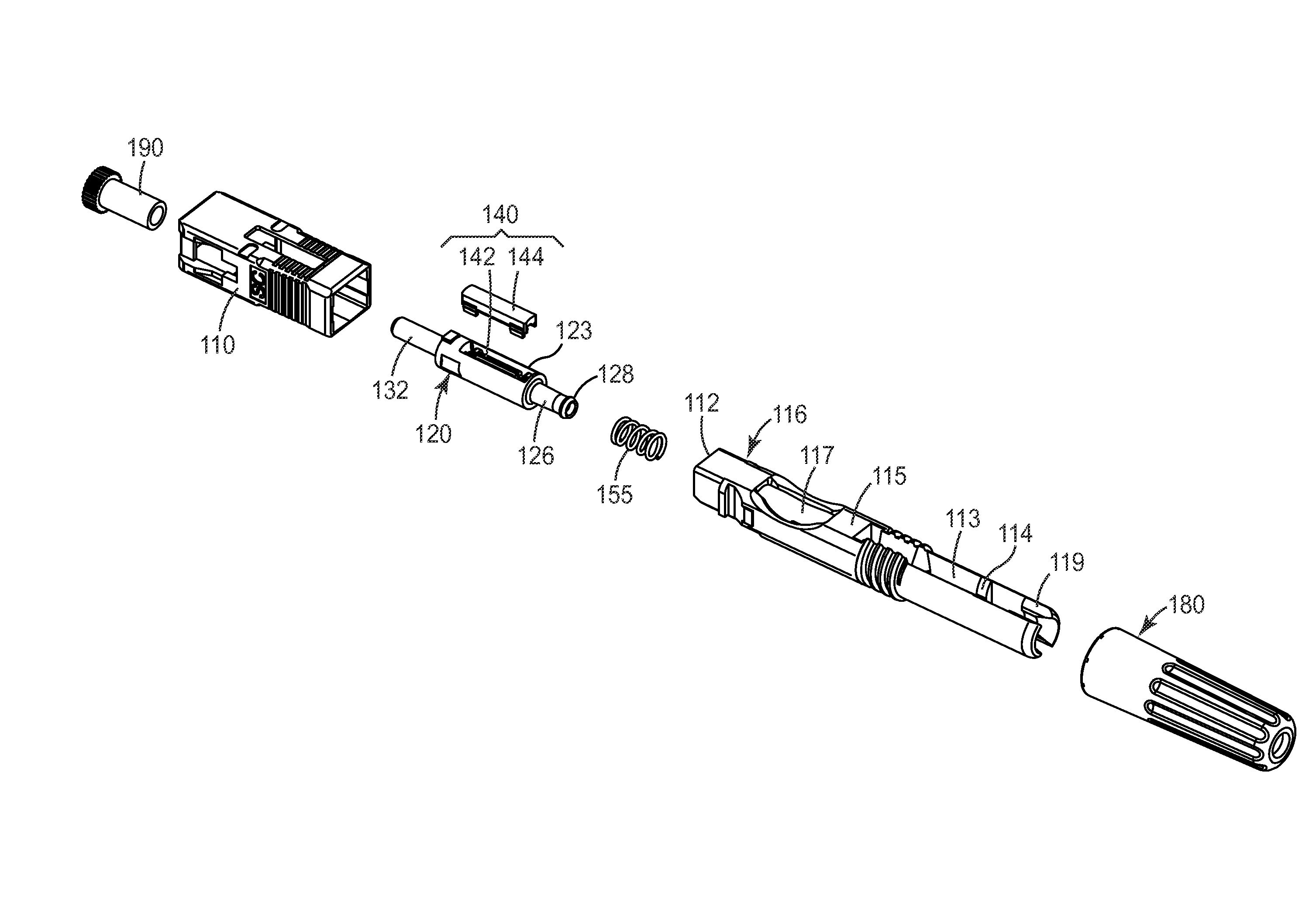
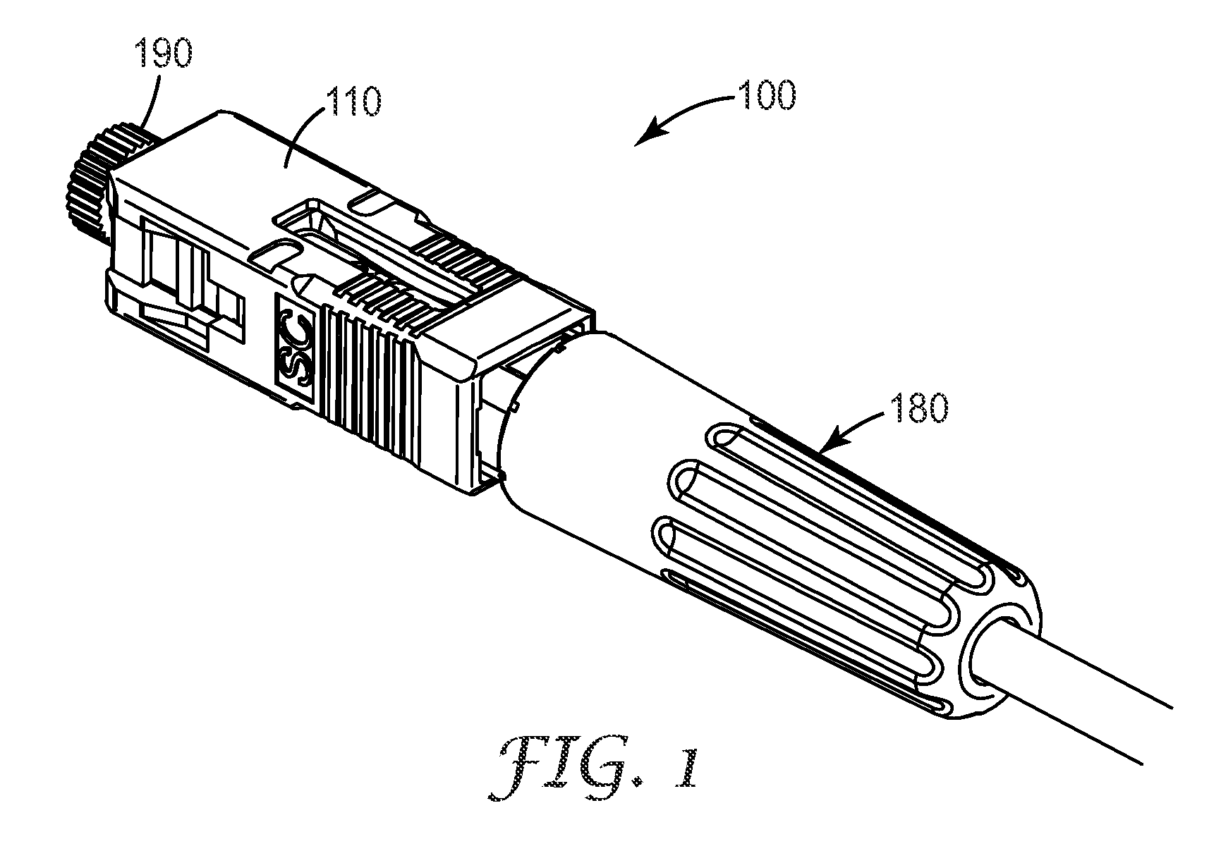
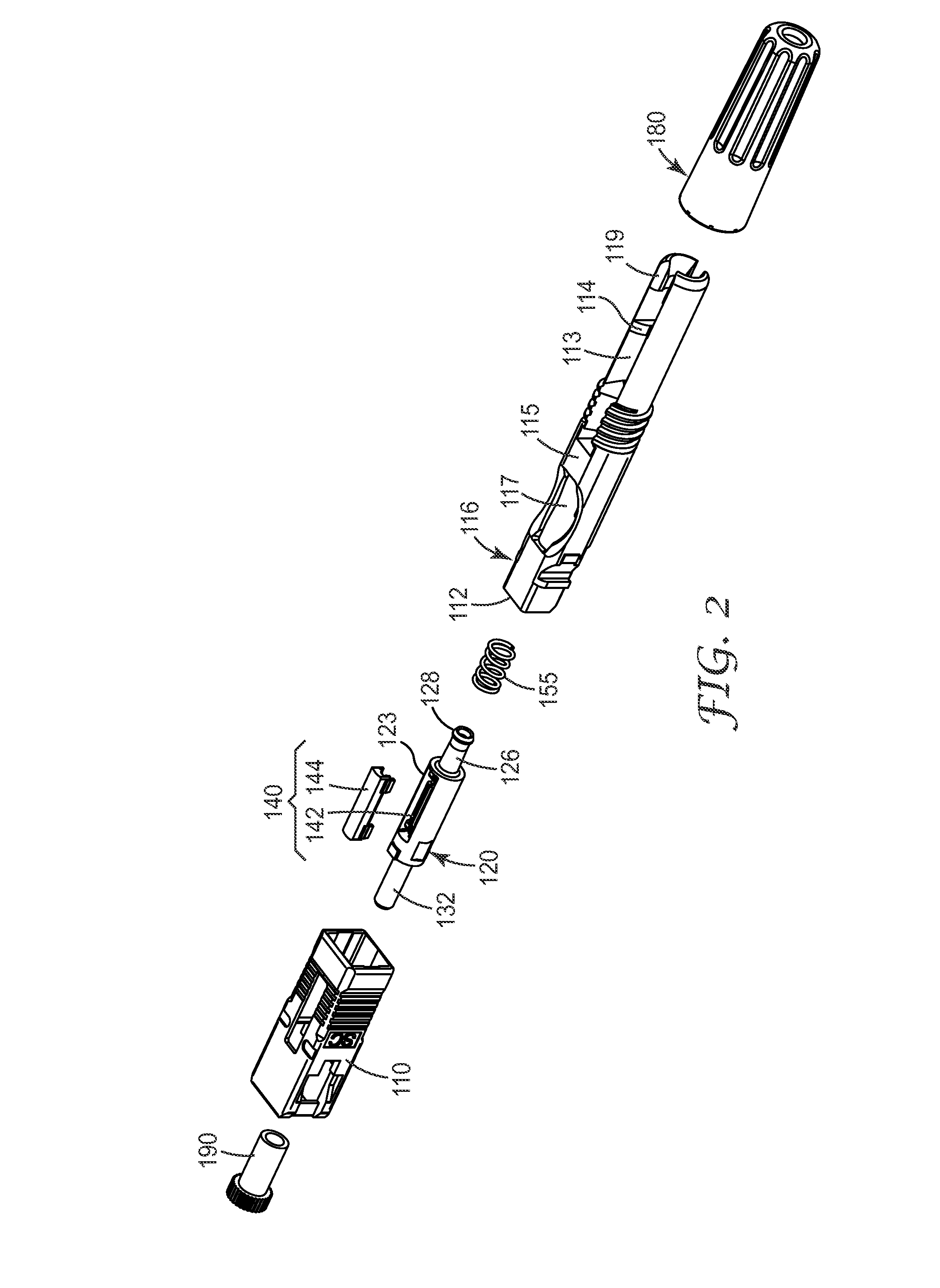
[0021]The present invention is directed to an optical fiber connector. In particular, the optical fiber connector of the exemplary embodiments is of compact length and is capable of straightforward field ...


PUM


Abstract

An optical fiber connector includes a housing configured to mate with a receptacle, a collar body that includes a fiber stub and a mechanical splice device, a backbone to retain the collar body within the housing, and a boot. The backbone includes a fiber jacket clamping portion to clamp a jacket portion that surrounds a portion of the terminated optical fiber upon actuation. The boot actuates the fiber jacket clamping portion of the backbone upon attachment to the backbone. The optical fiber connector can be terminated in the field without the need to use a separate termination platform or tool.

Description

BACKGROUND[0001]1. Field of the Invention[0002]The present invention is directed to an optical fiber connector.[0003]2. Related Art[0004]Mechanical optical fiber connectors for the telecommunications industry are known. For example, LC, ST, FC, and SC optical connectors are widely used.[0005]However, commercially available optical fiber connectors are not well suited for field installations. Typically, an adhesive is required to mount these types of connectors on to an optical fiber. This process can be awkward and time consuming to perform in the field. Also post-assembly polishing requires that the craftsman have a higher degree skill.[0006]Also known are hybrid optical fiber splice connectors, as described in JP Patent No. 3445479, JP Application No. 2004-210251 (WO 2006 / 019516) and JP Application No. 2004-210357 (WO 2006 / 019515). However, these hybrid splice connectors are not compatible with standard connector formats and require significant piecewise assembly of the connector ...

Claims


Application Information

Patent Timeline
Patent Type & Authority Applications(United States)
IPC IPC(8): G02B6/36
CPCG02B6/3821G02B6/3887G02B6/3846G02B6/3888
Inventor LARSON, DONALD K.PARK, CHANSOOL
Owner CORNING RES & DEV CORP
Why Eureka
Try Eureka