
Apparatus for severing and collecting iv tubing tips

a tubing tip and accessory technology, applied in the direction of dough shaping, manufacturing tools, and catheters, can solve the problems of significant cost, significant time period, and negative impact on the throughput of molds

Active Publication Date: 2011-02-24
VANTE
View PDF14 Cites 2 Cited by
  • Summary
  • Abstract
  • Description
  • Claims
  • Application Information

AI Technical Summary

Benefits of technology

The present invention is an apparatus for making IV tubing with a machine that can quickly and easily change components to perform different functions. The machine has a spool for supporting tubing, a mold for forming the tubing, and a manifold for cooling the mold. The machine also has a passageway for collecting the severed tips of the tubing. The invention allows for the efficient and reliable production of IV tubing with severed tips.

Problems solved by technology

Such heating has been at a fixed location on the mold without the capability of varying the location of application of heat.
Nevertheless, a significant time period is required to achieve the requisite cooling of the mold to permit withdrawal of the formed tubing.
Such time constraints negatively impact throughput of the mold.
Without the capability of using substitutable subassemblies related to the mold itself, significant costs are incurred by having to develop a complete unit for each type of operation to be achieved.
Despite the maturity of the IV tip manufacturing process, there does not exist a reliable and consistent apparatus or methodology for capturing excess material resulting from the tip cutting process.
In a typical IV tip manufacturing clean room, small particulates, byproducts of IV tip cuttings, cover the surroundings of an IV tipping station and demonstrates the lack of existing methodology to capture this debris.
Such system failures may be indicative of production of bad parts.
In an automated environment, a failure of this type may be a significant set back.

Method used


Image

  • Apparatus for severing and collecting iv tubing tips
  • Apparatus for severing and collecting iv tubing tips
  • Apparatus for severing and collecting iv tubing tips

Examples


Embodiment Construction

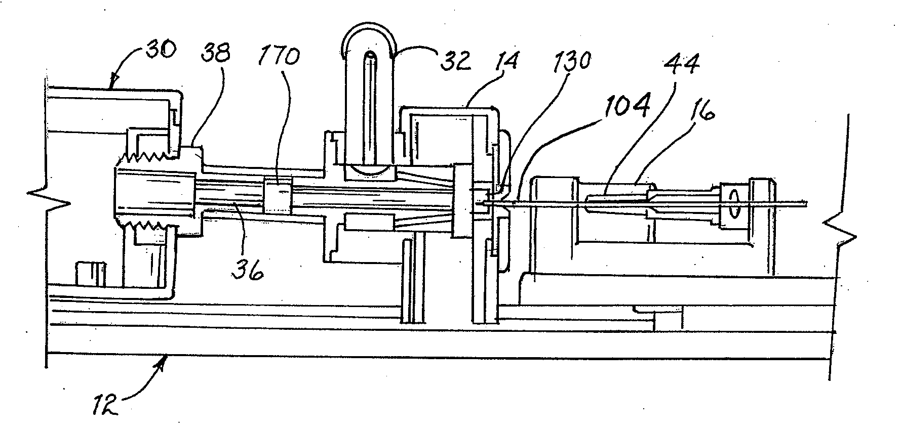
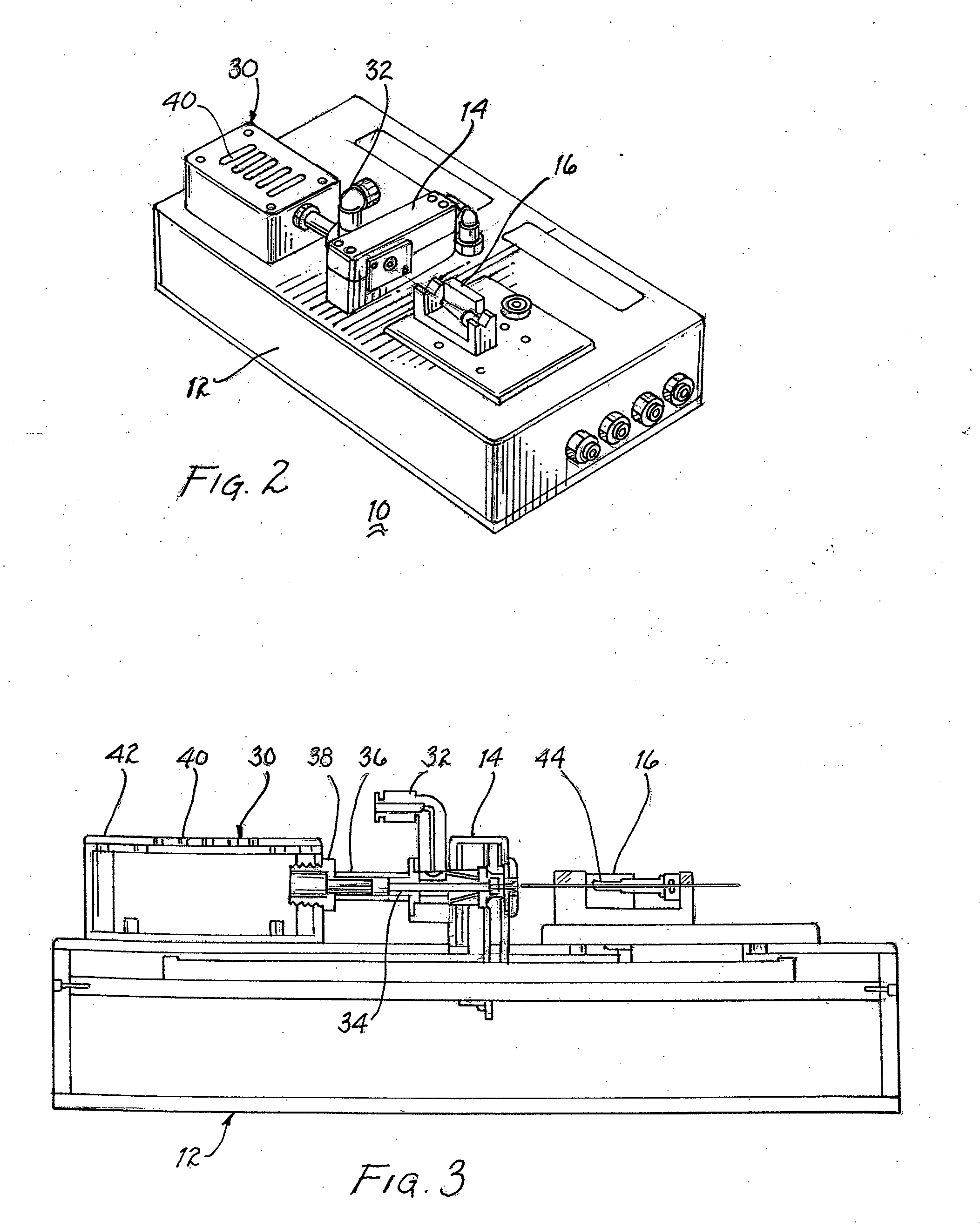
[0040]In the formation of IV tubing, sometimes referred to as a cannula tip or a stylet tip, the end of the tubing is tapered and the tip is cut off. The cut off tip amounts to debris to be discarded. In a production run, it is important to identify the presence of each cut off tip to ensure that the IV tubing is properly formed and that the manufacturing process is functioning normally. The apparatus for forming the IV tubing includes a source of air flow for cooling the attendant low mass mold. The air flow is also channeled through passageways to urge translation of the cut off tips past sensors for detecting the presence of cut off tips and into a collection chamber.

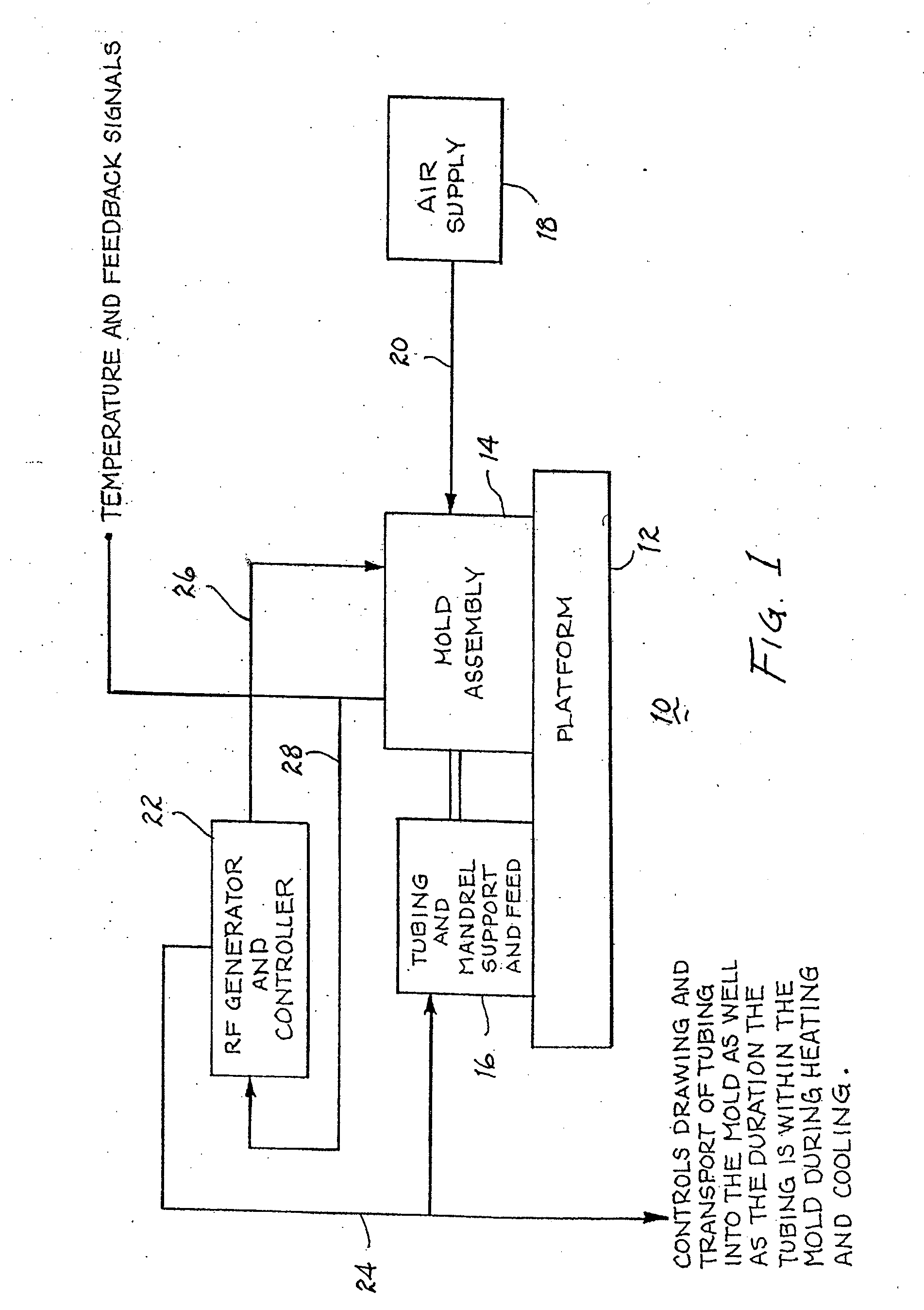
[0041]FIG. 1 illustrates a mold apparatus 10 for forming IV tubing. In particular, a platform or housing 12 supports mold assembly 14. The insertion and withdrawal of a mandrel, along with insertion and withdrawal of plastic tubing, into and from a mold assembly is provided by a support and feed unit 16. It is to be ...


PUM

PropertyMeasurementUnit
lengthaaaaaaaaaa
areaaaaaaaaaaa
heataaaaaaaaaa

Abstract

Mandrel supported IV tubing is inserted within a mold of a mold assembly to heat the IV tubing and form a tapered end of the tubing. The tip of the tubing extending beyond the tapered end of the tubing is severed by the mandrel bearing against the mold to lodge the tip in an outlet of the mold. Cooling air is introduced to the mold assembly to cool the mold and to create a flow of turbulent air about the outlet of the mold to extract the severed tips. The turbulent air is exhausted through a channel, pipe and fitting into a collection chamber and causes translation of the severed tip to and into the collection chamber. Sensors may be incorporated to sense the translation of the severed tips.

Description

CROSS REFERENCE TO RELATED APPLICATIONS[0001]The present application is a divisional of an application entitled “METHOD AND APPARATUS FOR COLLECTING IV TUBING TIPS” filed Jul. 14, 2009 and assigned Ser. No. 12 / 502,620 which is related to and claims priority to a provisional application entitled “METHOD FOR RAPIDLY HEATING AND COOLING A MOLD” filed Jul. 18, 2008, and assigned Ser. No. 61 / 081,969 and is a continuation-in-part application of an application entitled “METHOD FOR RAPIDLY HEATING AND COOLING A MOLD” filed Apr. 14, 2008 and assigned Ser. No. 12 / 102,675 which is a divisional of an application entitled “APPARATUS FOR RAPIDLY HEATING AND COOLING A MOLD”, filed Oct. 31, 2006 and assigned Ser. No. 11 / 555,172, which in turn is related to and claims priority from a provisional patent application entitled “ASSEMBLY FOR RAPIDLY HEATING AND COOLING A CATHETER MOLD” filed Jan. 25, 2006 and assigned Ser. No. 60 / 762,204 and a further provisional application entitled “RAPID HEATING AND C...

Claims


Application Information

Patent Timeline
Patent Type & Authority Applications(United States)
IPC IPC(8): B29C57/00
CPCA61M25/0009B29B13/025B29L2031/7542B29K2101/12B29C2793/009B29C33/02B29C33/04B29C33/06B29C37/0003B29C65/18B29C65/32B29C66/0342B29C66/1122B29C66/347B29C66/5221B29C2035/0811B29C2035/1658B29C65/00
Inventor AUGUSTINE, JOSEPH G.
Owner VANTE
Learn More