Particle capture devices and methods of use thereof

a technology which is applied in the field of particle capture and particle pairing, can solve the problems of lack of defined positions, inability to capture and pair particles in isolated positions, and low yield, and achieve the effect of facilitating fluid communication

Active Publication Date: 2011-02-24
MASSACHUSETTS INST OF TECH +1
View PDF4 Cites 87 Cited by
  • Summary
  • Abstract
  • Description
  • Claims
  • Application Information

AI Technical Summary

Benefits of technology

[0018]In one embodiment, the additional opening is positioned between the first and second cham

Problems solved by technology

Currently, an ability to capture and pair particles in isolated, defined positions and with high yield is lacking.
However, such binding/c

Method used


Image

  • Particle capture devices and methods of use thereof
  • Particle capture devices and methods of use thereof
  • Particle capture devices and methods of use thereof

Examples


example 1

An Embodiment of a Capture-Comb Device of this Invention

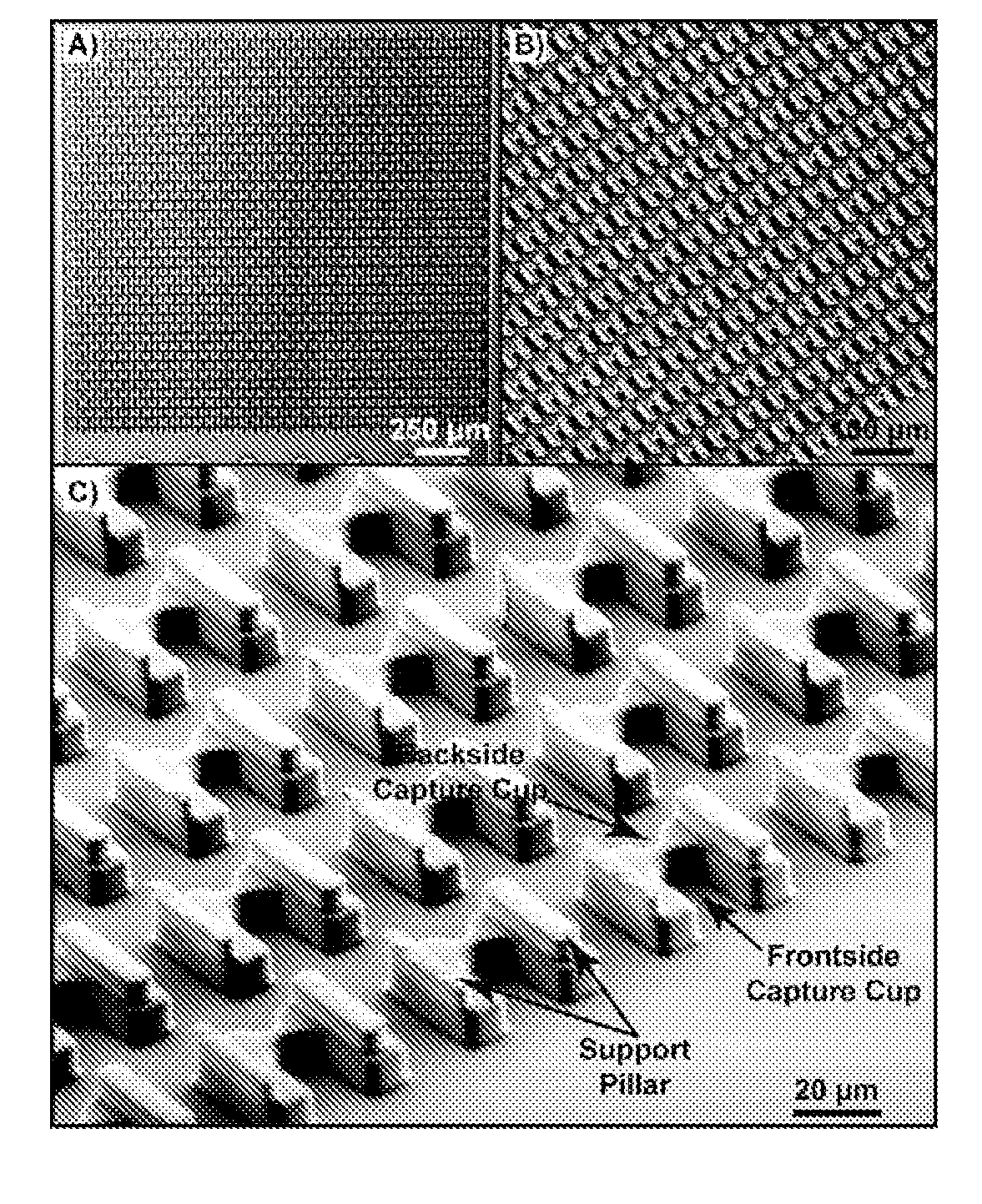
[0257]An embodiment of a device of this invention, comprising a two-cell Capture and pair device was fabricated as part of a microfluidic system (FIG. 1). The capture-and pair device comprised a microfluidic chamber with an array of capture units, each capture unit holding two chambers. The two chambers were positioned back to back within each capture unit. The opening of the two chambers were oriented in and against the direction of a fluid flow, respectively (see FIGS. 1 and 2). The two chambers in each capture unit differed in size.

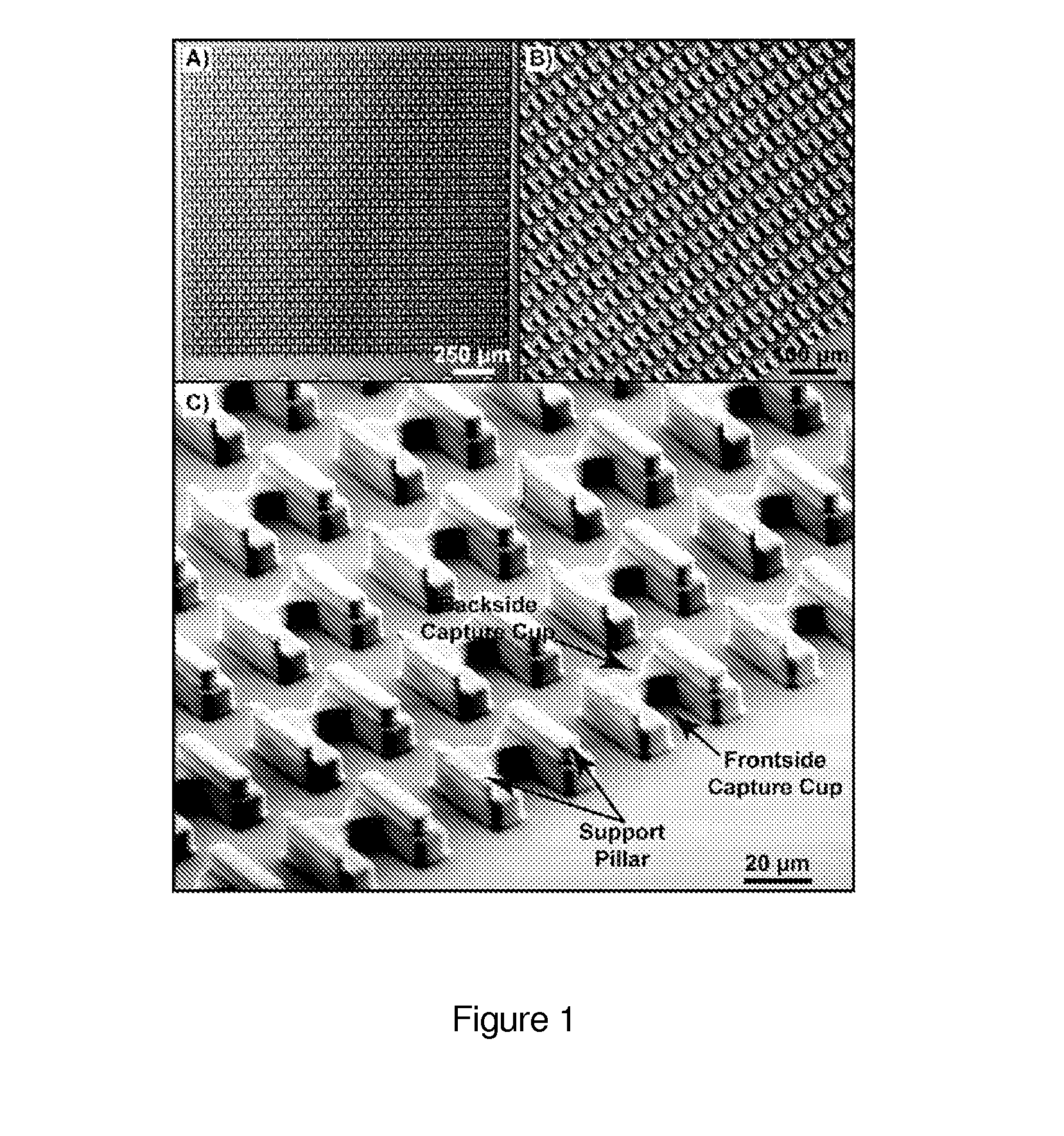
[0258]The elements of an embodiment of this device are schematically depicted in FIG. 2. According to this aspect, 2 chambers (2-20; 2-30) are so positioned within the capture unit (2-10) such that openings of each chamber faces opposing directions. The first chamber has a smaller depth (2-20), while on an opposite face of the unit, the second chamber having a larger depth is positioned (2-30). Th...

example 2

Capture and Pair of Two Different Cell Types

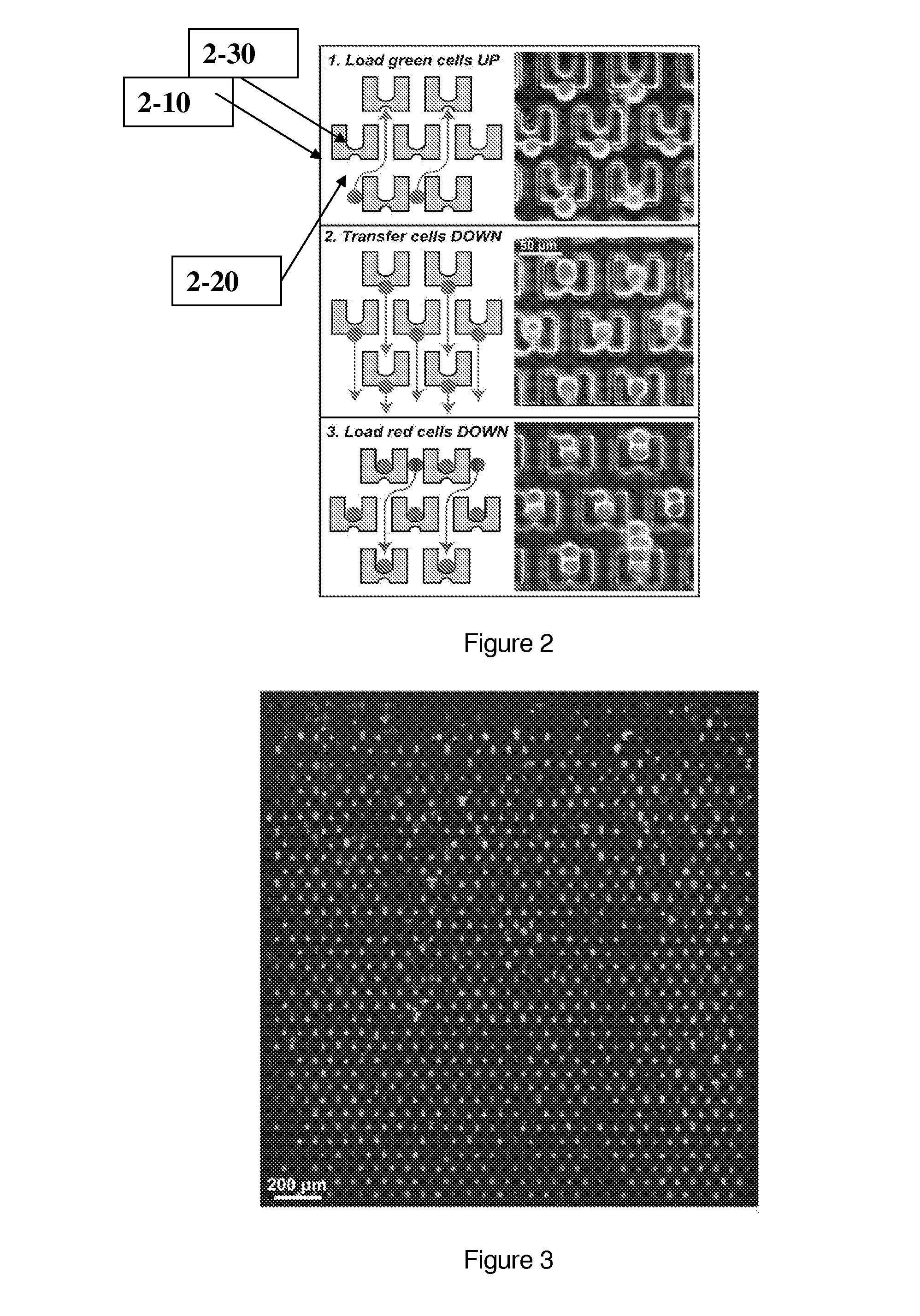
[0263]FIG. 2 (right panel) and FIG. 3 are fluorescent overlay images. Cells were applied to the device and captured in the chambers as described in Example 1, representing an embodiment of a method of the present invention. Red and green NIH 3T3 cells were loaded sequentially as described above. Cells were labeled with CellTracker® green and orange. In some embodiments 3T3s were used with stably-integrated GFP and RFP. In some embodiments GFP-positive mouse embryonic stem cells and Hoechst-stained mouse embryonic fibroblasts were used. In other embodiments, GFP-positive mouse B-cells and unstained myeloma cells were used.

[0264]Cells of a first type (green) were loaded in a direction where fluid flow was in a direction opposite to the openings of the first chambers in the capture device, thus cells were trapped in the first, smaller chambers. Fluid flow direction was then reversed such that the trapped cells within the first chamber were th...

example 3

Two-cell Capture-Comb Device for Attaching Fluorescent Tags to Cells

[0265]A two-cell Capture-comb device as described in Example 1 is fabricated. A mixture of cells of a first type is loaded in the device and cells are transferred to capture units of larger dimensions as described in Example 1. Fluorescent beads or quantum dots are introduced into the device as described in FIG. 1C, whereby the beads or dots are introduced to the capture units of larger dimensions comprising the initially loaded cells. The dimensions of the capture units are constructed such that each capture unit can only hold one cell and one bead or quantum dot. The beads or quantum dots, in some embodiments, are functionalized, so that they specifically interact with the cells. Upon release of the cells from the device by reversing fluid flow, as described, released cells are conjugated to the beads or quantum dots.


PUM


Abstract

The present invention provides a device and methods of use thereof in microscale particle capturing and particle pairing. This invention provides particle patterning device, which mechanically traps individual particles within first chambers of capture units, transfer the particles to second chambers of opposing capture units, and traps a second type of particle in the same second chamber. The device and methods allow for high yield assaying of trapped cells, high yield fusion of trapped, paired cells, for controlled binding of particles to cells and for specific chemical reactions between particle interfaces and particle contents. The device and method provide means of identification of the particle population and a facile route to particle collection.

Description

GOVERNMENT INTEREST STATEMENT[0001]This invention was made in whole or in part with government support under EB007278 and 5-R37-CA084198 awarded by the National Institutes of Health and under DL-H-551059 awarded by the National Aeronautics and Space Administration. The government may have certain rights in the invention.FIELD OF THE INVENTION[0002]This invention provides devices and methods of use thereof in particle capturing and particle pairing.BACKGROUND OF THE INVENTION[0003]Systematic investigation and understanding of small particles and biological cells depends on the tools available with which to probe particle or cell function. An important aspect of cell function is the interaction between two cells. Such interaction occurs at the interface and requires close contact between the two cells. Interaction between cells involves signaling, exchange of membrane material, exchange of intracellular material and fusion of the cells. For particles other than cells, interfacial inte...

Claims


Application Information

Patent Timeline
IPC IPC(8): C40B30/00C40B60/00C40B50/14C40B30/06
CPCB01L3/502761B01L2200/0647B01L2200/0668B01L2200/10G01N33/5005B01L2300/0645B01L2300/16B01L2400/0421B01L2400/0424B01L2200/12
Inventor VOLDMAN, JOELSKELLEY, ALISON M.KIRAK, OKTAYJAENISCH, RUDOLF
Owner MASSACHUSETTS INST OF TECH
Why Eureka
Try Eureka