Self-regulating transcutaneous energy transfer

a transcutaneous energy and self-regulation technology, applied in the field of implantable medical devices, can solve the problems of overheating of implants, damage to patient tissue, and unacceptable increase of charging tim

Active Publication Date: 2011-02-24
ST CROIX MEDICAL
View PDF15 Cites 110 Cited by
  • Summary
  • Abstract
  • Description
  • Claims
  • Application Information

AI Technical Summary

Benefits of technology

[0026]An embodiment is an implantable device for receiving electrical power from an external charger unit, the external charger unit producing an oscillating current in a primary coil at a driving frequency, the oscillating current producing an oscillating magnetic field proximate the external charger unit, the implantable device comprising: a secondary coil for receiving the oscillating magnetic field and producing an alternating current at the driving frequency, the amplitude of the alternating current depending in part on a resonant profile of the secondary coil, on the driving fr

Problems solved by technology

More recently developed hearing aids that use rechargeable batteries may last only about six to twelve weeks between recharging sessions, but the recharging sessions are simple, quick, inexpensive, non-invasive, and are completely painless.
If left unchecked, such excess power can lead to overheating of the implant, which can exceed the mandated temperature standard and may even damage the tissue of the patient, which would be unacceptable.
Although this first example ensures that the amount of power co

Method used


Image

  • Self-regulating transcutaneous energy transfer
  • Self-regulating transcutaneous energy transfer
  • Self-regulating transcutaneous energy transfer

Examples


Embodiment Construction

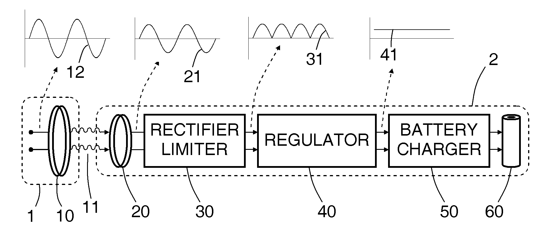
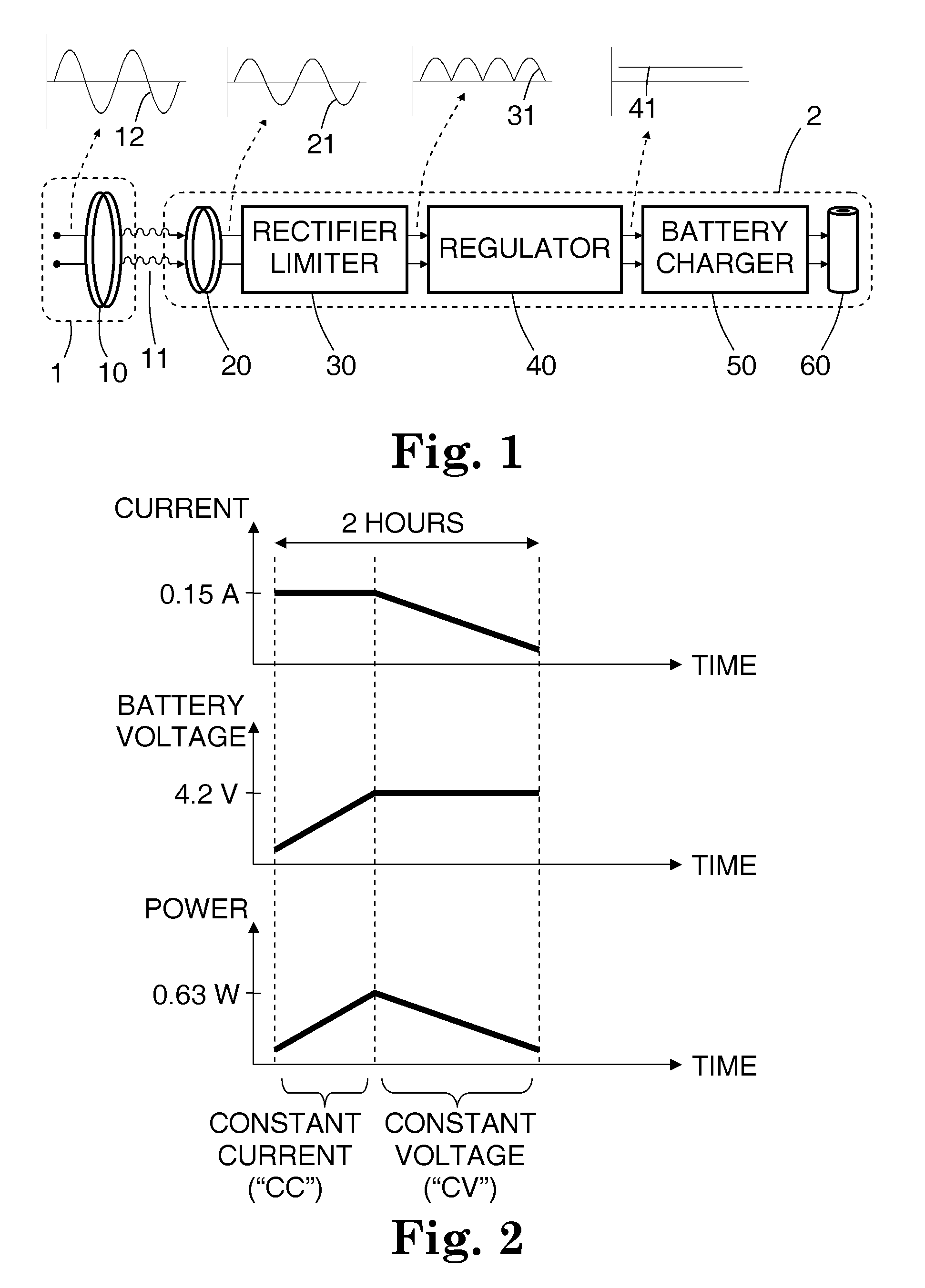
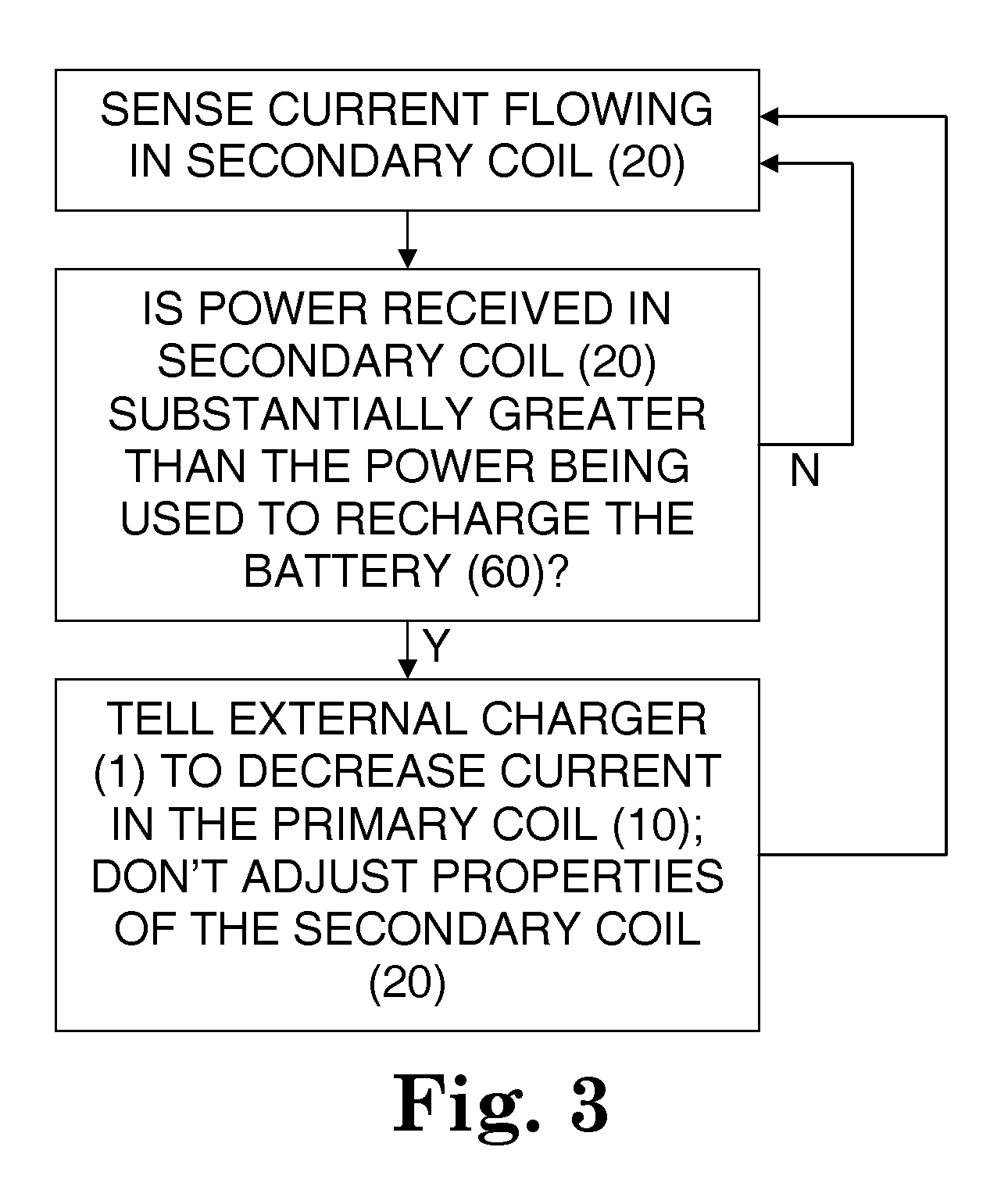
[0038]A rechargeable battery system and method are disclosed, in which an implantable medical device (IMD) regulates its transfer of energy from a separate charger unit. For recharging, a charger unit is brought into proximity to the implanted device. An oscillating current is generated in a primary coil, located in the charger. By inductive coupling through an oscillating magnetic field, an alternating current is generated in a secondary coil, which is implanted in or near the implanted device. The alternating current then passes through a half-wave or full-wave rectifier to form a one-sided current, then passes through a regulator to form an essentially direct current, which is in turn directed to the rechargeable battery in the implanted device.

[0039]The secondary coil has a controllable damped resonant frequency, which can be dynamically tuned away from the driving frequency of the primary coil by a variable resistor and / or by varying a duty cycle of a rapidly switched electrica...


PUM


Abstract

A rechargeable battery system and method are disclosed, in which an implantable medical device (IMD) regulates its transfer of energy from a separate charger unit. For recharging, a charger unit is brought into proximity to the implanted device. An oscillating current is generated in a primary coil, located in the charger. By inductive coupling through an oscillating magnetic field, an alternating current is generated in a secondary coil, which is implanted in or near the implanted device. The alternating current then passes through a half-wave or full-wave rectifier to form a one-sided current, then passes through a regulator to form an essentially direct current, which is in turn directed to the rechargeable battery in the implanted device. The secondary coil has a controllable damped resonant frequency, which can be dynamically tuned away from the driving frequency of the primary coil by a variable resistor and/or by varying a duty cycle of a rapidly switched electrical element. If a control loop in the implant senses that more power is being received at the second coil than is actually being used to recharge the battery, the control loop temporarily changes the variable resistance. When this happens, the resonant frequency of the secondary coil is detuned slightly away from the driving frequency, so that less of the incoming power is absorbed by the secondary coil. Alternatively, the secondary coil may be temporarily short-circuited. With less or no excess power entering the circuitry of the implant, the problem of overheating is mitigated.

Description

CROSS-REFERENCE TO RELATED APPLICATIONS[0001]Not ApplicableSTATEMENT REGARDING FEDERALLY SPONSORED RESEARCH OR DEVELOPMENT[0002]Not ApplicableBACKGROUND OF THE INVENTION[0003]1. Field of the Invention[0004]The present invention is directed to implantable medical devices, and more particularly to recharging of batteries in implantable medical devices.[0005]2. Description of the Related Art[0006]For electrical medical devices that are surgically implanted within the body of a patient, a recent improvement is the development of rechargeable batteries. Rather than undergoing surgery to remove or replace a device that has a dead battery, a patient may now undergo periodic recharging sessions, which are far less invasive and far less expensive.[0007]For instance, a typical first-generation implantable hearing aid may last around six to nine years with its non-rechargeable battery. More recently developed hearing aids that use rechargeable batteries may last only about six to twelve weeks ...

Claims


Application Information

Patent Timeline
IPC IPC(8): A61N1/378
CPCH02J7/025A61N1/3787H02J7/00716H02J7/007182H02J7/0071H02J50/80H02J50/90H02J50/10H02J2310/23H02J50/12
Inventor MAZANEC, PAUL RICHARD
Owner ST CROIX MEDICAL
Why Eureka
Try Eureka