Controller and system including a controller for detecting a failure thereof

Inactive Publication Date: 2011-02-24
EATON CORP
View PDF13 Cites 30 Cited by
  • Summary
  • Abstract
  • Description
  • Claims
  • Application Information

AI Technical Summary

Benefits of technology

[0034]In accordance with aspects of the disclosed concept, when a controller opening is initiated, regardless of the reason, and current (e.g., single-phase or three-phase current) continues to flow, a controller output is activated that is structured to cause a remote circuit interrupter to open a power circuit electrically connected in series with the separable contacts of the controller. A

Problems solved by technology

During maintenance of known vacuum contactors to replace a number of failed components, coils, coil magnets, armature stop assemblies, auxiliary contact assemblies, vacuum interrupters and/or other components might fail and/or be incorrectly replaced.
Such failures and/or incorrect replacements might not be apparent to the user until after the vacuum contactor suffers a subsequent failure (e.g., without limitation, contact welding).
For example, a kick-out spring can break, contactor latch mechanisms can fail to unlatch, or a sticky substance can get between an armature plate and a coil core, thereby not allowing the kick-out spring to open the vacuum interrupters and interrupt the load current.
In this instance, the vacuum contactor can no longer protect the load or its power circuit.
However, when a second vacuum interrupter looses vacuum, the two failed vacuum interrupters continue to arc.
This will break the ceramic enclosures of the two failed vacuum interrupters, which, in turn, can cause phase-to-phase arcing and arcing to the enclosure.
At the same time, the motor can be single-phased and might be damaged, burn up or otherwise be destroyed before fuses or other upstream protective devices interrupt the failure.
This is time consuming, expensive, requires bulky, expensive equipment and skilled technicians, and can only occur during extended maintenance down times. As a result, many vacuum losses go undetected until a second vacuum interrupter fails.
This event always result

Method used


Image

  • Controller and system including a controller for detecting a failure thereof
  • Controller and system including a controller for detecting a failure thereof
  • Controller and system including a controller for detecting a failure thereof

Examples


example 1

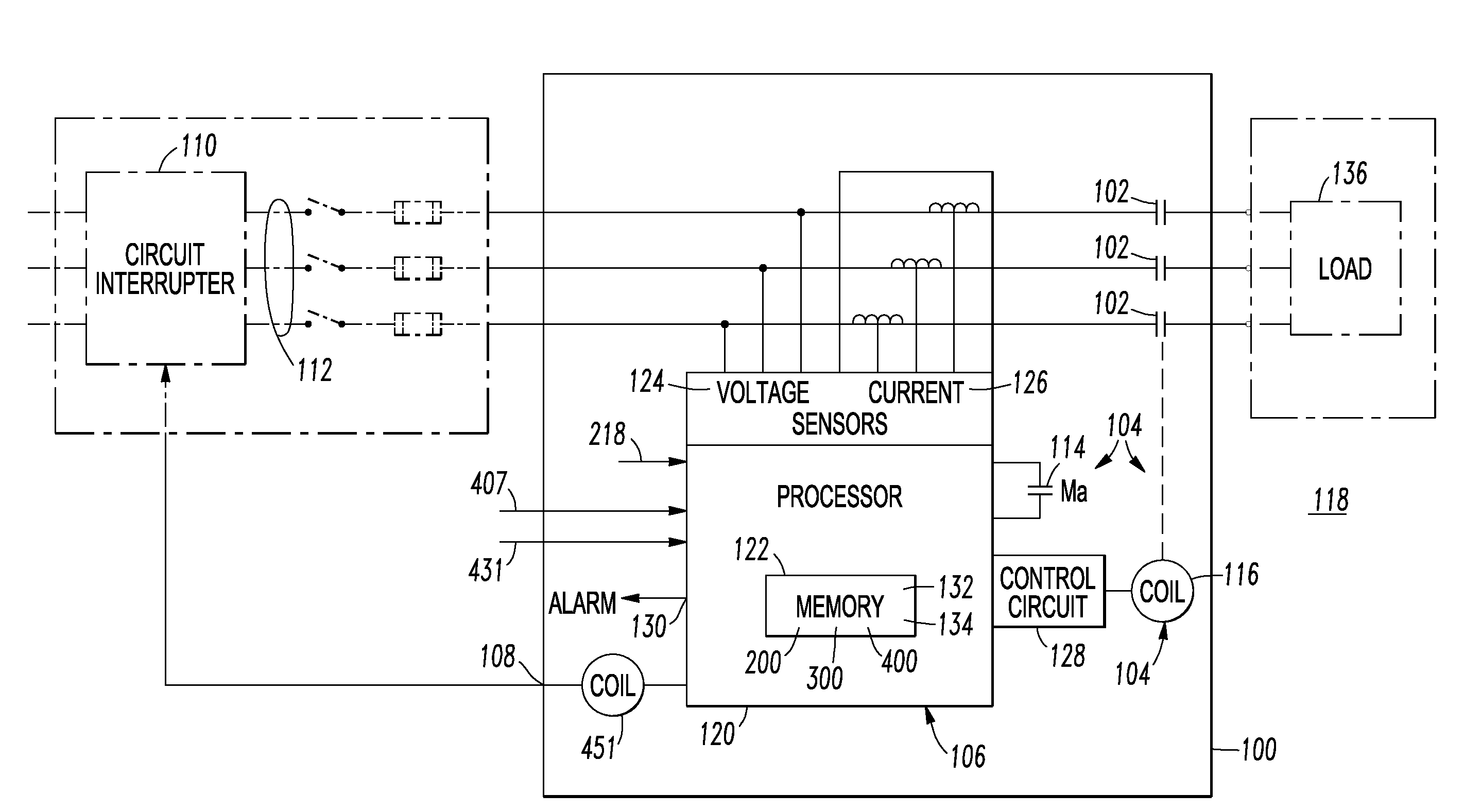
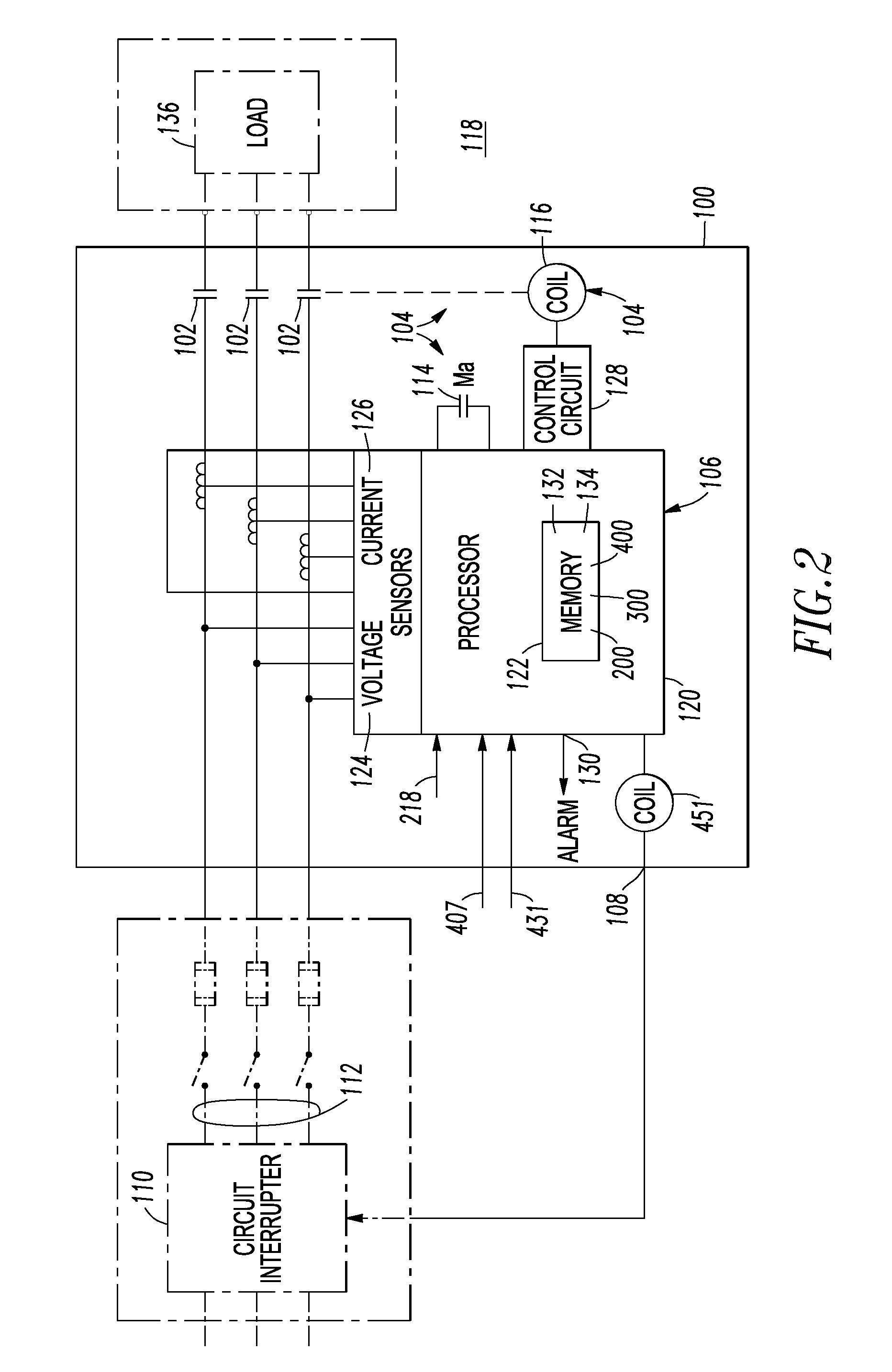
[0069]As is conventional, the example operating mechanism 104 can include auxiliary contacts 114 (Ma) structured to indicate an open state or a closed state of the separable contacts 102 as controlled by the coil 116. Although one coil 116 is shown, the disclosed concept is applicable to contactors having any number of coils (e.g., without limitation, a close coil; an open coil; a mechanical latch coil).

example 2

[0070]A system 118 includes the remote circuit interrupter 110, the power circuit 112 and the contactor 100. The circuit interrupter 110 is upstream of the contactor 100 and responsive to the output 108 thereof. The circuit interrupter 110 is structured to open the power circuit 112 electrically connected in series with the separable contacts 102 responsive to the activated output 108 of the contactor 100.

example 3

[0071]The example processor circuit 106 can include a processor 120, a memory 122, a first sensor 124 structured to sense voltage operatively associated with the separable contacts 102, and a second sensor 126 (e.g., without limitation, a number of Rogowski coils) structured to sense current flowing through the separable contacts 102. The processor circuit 120 cooperates with the coil 116 to open and close the separable contacts 102. The processor circuit 120 or operating mechanism 104 preferably includes the control circuit 128 controlled by the processor 120. The control circuit 128 is structured to cause the coil 116 to open and close the separable contacts 102. The processor 120 is structured to detect failure of the separable contacts 102 (e.g., a number of vacuum interrupters) and / or the auxiliary contacts 114 and activate the output 108 and / or an alarm output 130.

[0072]The processor circuit 106, the control circuit 128 and the sensors 124,126 may or may not be part of the con...


PUM


Abstract

A controller for a load includes separable contacts, an operating mechanism structured to open and close the separable contacts, a processor circuit cooperating with the operating mechanism to open and close the separable contacts, and an output controlled by the processor circuit. The output is structured to cause a remote circuit interrupter to open a power circuit electrically connected in series with the separable contacts. The processor circuit is structured to detect failure of the controller to control the load and activate the output.

Description

BACKGROUND[0001]1. Field[0002]The disclosed concept pertains generally to electrical switching apparatus and, more particularly, to controllers. The disclosed concept also relates to systems including a controller.[0003]2. Background Information[0004]Contactors are employed, for example and without limitation, in starter applications to switch on / off a load as well as to protect a load, such as a motor or other electrical device, from current overloads. Contactors are used as electrical switching apparatus and incorporate fixed and movable contacts that when closed, conduct electric power.[0005]For example, three-pole, low voltage contactors have three contact assemblies, one contact assembly for each phase or pole of a three-phase electrical device. Each contact assembly can include, for example, a pair of stationary contacts and a moveable contact. One stationary contact is a line side contact and the other stationary contact is a load side contact. The moveable contact is control...

Claims


Application Information

Patent Timeline
IPC IPC(8): G06F1/28
CPCG01R31/3277H01H47/002H01H33/668H01H33/6662
Inventor KELLIS, JOE M.FARR, LAWRENCE B.
Owner EATON CORP
Why Eureka
Try Eureka