Card holder

a card and card holder technology, applied in the direction of identification means, medals, show cards, etc., can solve the problems of hard for users, easy to damage the clip, inconvenient to read the information on the card, etc., and achieve the effect of convenient attachment or removal from the bearer's garmen

Active Publication Date: 2011-03-03
FOK SHEK HUNG
View PDF4 Cites 0 Cited by
  • Summary
  • Abstract
  • Description
  • Claims
  • Application Information

AI Technical Summary

Benefits of technology

[0005]A main object of the present invention is to provide a durable card holder, which can be easily attached to o

Problems solved by technology

The user shall heavily press the wings for attaching or removing the holder from the clothing, which is very hard for the user.
The clip is easily destroyed under such strongly and repeatedly pressing operation as well.
Furthermore,

Method used


Image

  • Card holder
  • Card holder
  • Card holder

Examples


Embodiment Construction

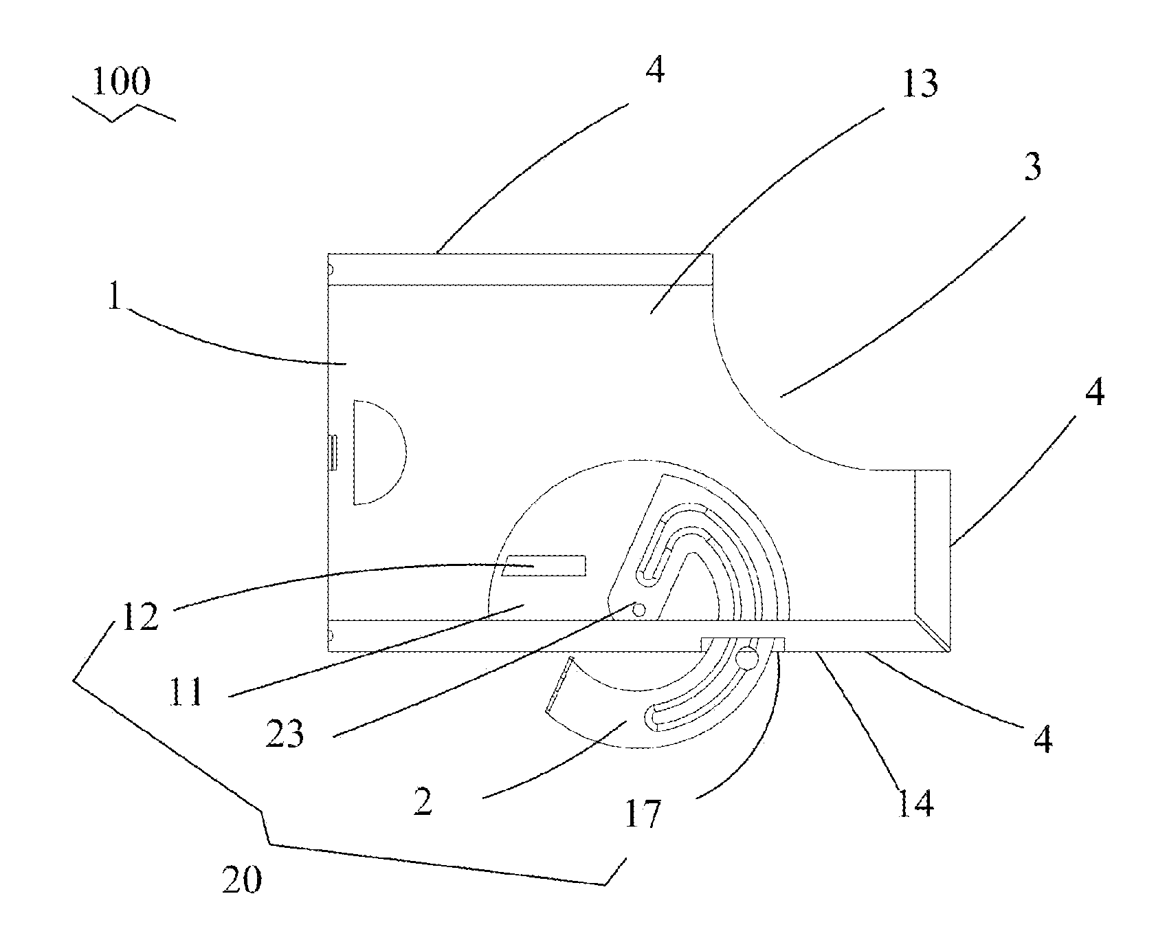
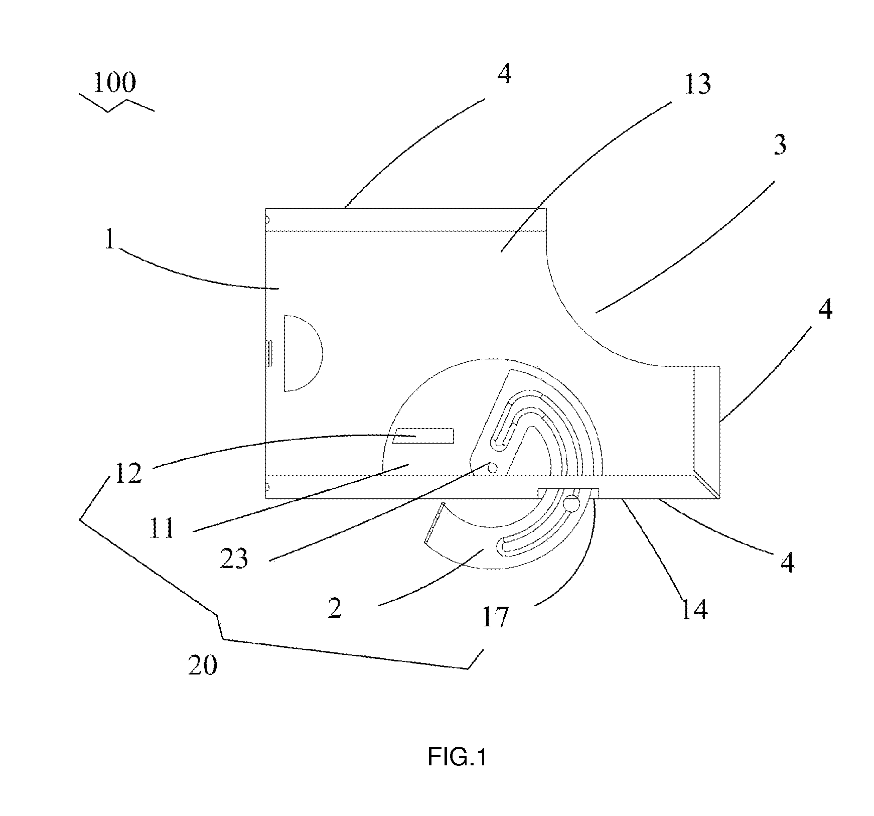
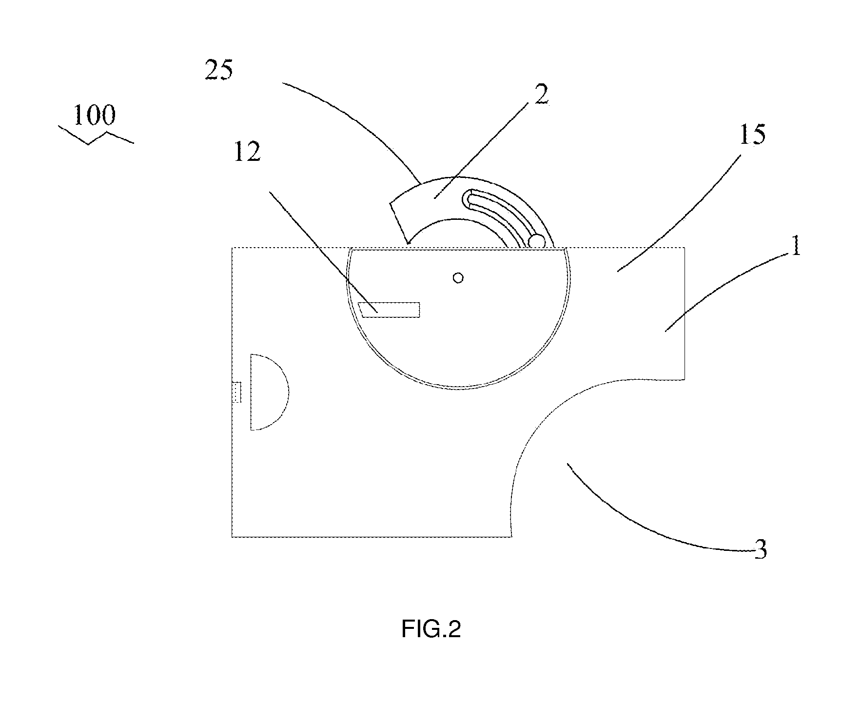
[0016]Referring to FIGS. 1 and 2, a card holder 100 according to the embodiment of the present invention includes a base 1 and a clamping means 20. The base 1 is used to bear card thereon, and the clamping means 20 attachs the holder 100 to garment. The base 1 has a first face 13 and an opposite second face 15. In a preferable embodiment, the base 1 is substantially in a shape of rectangle (but not limited to). A flange 4 extends substantially around and outwards of the first face 13. In a preferable embodiment, the flange 4 extends fully around three edges of the first face 13, but only partially at a corner of the rectangular shape. The part at the corner without the flange 4 forms a cut-away portion 3, which is designed for card reading machines to easily and sensitively read the information from the card. A card is inserted onto the first face 13 of the base 1 and is grasped by the flange 4. It is understood that the cut-away portion 3 can be adaptably configured at any edge or ...


PUM


Abstract

A card holder (100) includes a base (1) and a clamping means (20) to attach the card holder to garment. A card is grasped on the base. The base has a first face (13) and an opposite second face (15). The clamping means includes a clamp (2) and a slot (12) for locking the clamp. The slot is defined in the base. The clamp is rotatably mounted to the base with an end retractably moving outwards. The retractably moving end can be locked in or released from the slot, so that the card holder can be attached to or removed from the bearer's garment in an easy way.

Description

BACKGROUND OF THE INVENTION[0001]The present invention relates to a holder for bearing cards, and especially to a holder for accommodating card therein and attaching to the bearer's garment with a kind of clamp[0002]In nowadays, we have various cards, such as identification card, bank card, metcard, business card, employees' nameplate, and etc., and many cards have a magnetic strip, microchip, or the like for storing important information of the bearer. It is known to provide bearer with a holder for such cards which can be attached to their clothing by way of a retractable spring clip. A well-known spring clip includes a pair of pressing wings which are assembled together with a spring so as to form a tip at an end thereof for snapping the bearer's clothing. Usually, the clip is very tight. The user shall heavily press the wings for attaching or removing the holder from the clothing, which is very hard for the user. The clip is easily destroyed under such strongly and repeatedly pr...

Claims


Application Information

Patent Timeline
IPC IPC(8): A44C3/00
CPCG09F3/20G09F1/10G09F3/207
Inventor HUNG, FOK SHEK
Owner FOK SHEK HUNG
Why Eureka
Try Eureka