Injection molded ferrule for cofired feedthroughs

a cofired feedthrough and injection molding technology, applied in the direction of electric discharge tubes, basic electric elements, electric apparatus, etc., can solve the problems of difficult and complex multi-step procedure to ensure the formation of reliable, high-quality electrical connections, and inability to use relatively large single-pin feedthroughs for many applications

Inactive Publication Date: 2011-03-03
MEDTRONIC INC
View PDF29 Cites 114 Cited by
  • Summary
  • Abstract
  • Description
  • Claims
  • Application Information

AI Technical Summary

Benefits of technology

[0010]In addition, a high integrity hermetic seal for medical implant applications prevents the ingress of body fluids into the IMD. Even a small leak rate of such body fluid penetration can, over a period of many years, build up and damage sensitive internal electronic components. This may cause catastrophic failure of the implanted device. The hermetic seal for medical implant (as well as space and military) applications is typically constructed of highly stable alumina ceramic or glass materials with very low bulk permeability. The above-described feedthroughs formed using traditional ceramic, glass, or metal-ceramic co-fired substrates generally require additional polymer protection to remain hermetic under implant conditions due to instability of the ceramic-to-metal interfaces in body fluids. This can cause both hermetic loss of the seal itself and cracking of the ceramic due to stresses that developed from brazing and welding processes.

Problems solved by technology

Consequently, use of relatively large single pin feedthroughs is no longer feasible for many applications, and numerous multiple conductor feedthroughs are used or proposed for use that fit within smaller sized case openings that provide two, three, four, or more conductors within a single ferrule.
Although feedthrough filter capacitor assemblies of the type described above have performed in a generally satisfactory manner, the manufacture and installation of such filter capacitor assemblies can be relatively time consuming and therefore costly.
For example, installation of the discoidal capacitor into the small annular space between the terminal pin and ferrule as shown in a number of these patents can be a difficult and complex multi-step procedure to ensure formation of reliable, high quality electrical connections.
Other problems have arisen when chip capacitors have been coupled to conductive trace and via pathways of co-fired multi-layer metal-ceramic substrates disclosed in the referenced '652, '358, '891, '476, '435, '926, and '906 patents.
The conductive paths of the feedthrough arrays and attached capacitors may suffer from high inductance, which may have the effect of failing to attenuate EMI and other unwanted signals, characterized as “poor insertion loss.”
Even a small leak rate of such body fluid penetration can, over a period of many years, build up and damage sensitive internal electronic components.
This may cause catastrophic failure of the implanted device.
The above-described feedthroughs formed using traditional ceramic, glass, or metal-ceramic co-fired substrates generally require additional polymer protection to remain hermetic under implant conditions due to instability of the ceramic-to-metal interfaces in body fluids.
This can cause both hermetic loss of the seal itself and cracking of the ceramic due to stresses that developed from brazing and welding processes.

Method used


Image

  • Injection molded ferrule for cofired feedthroughs
  • Injection molded ferrule for cofired feedthroughs
  • Injection molded ferrule for cofired feedthroughs

Examples


example 1

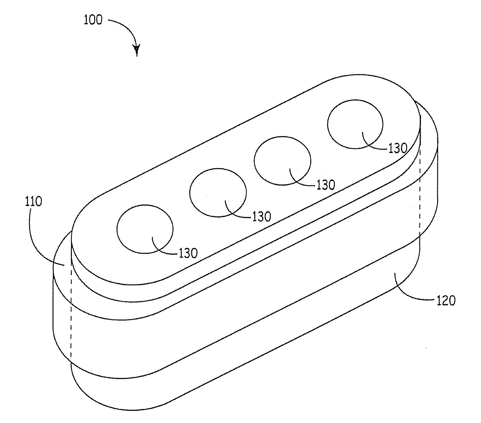
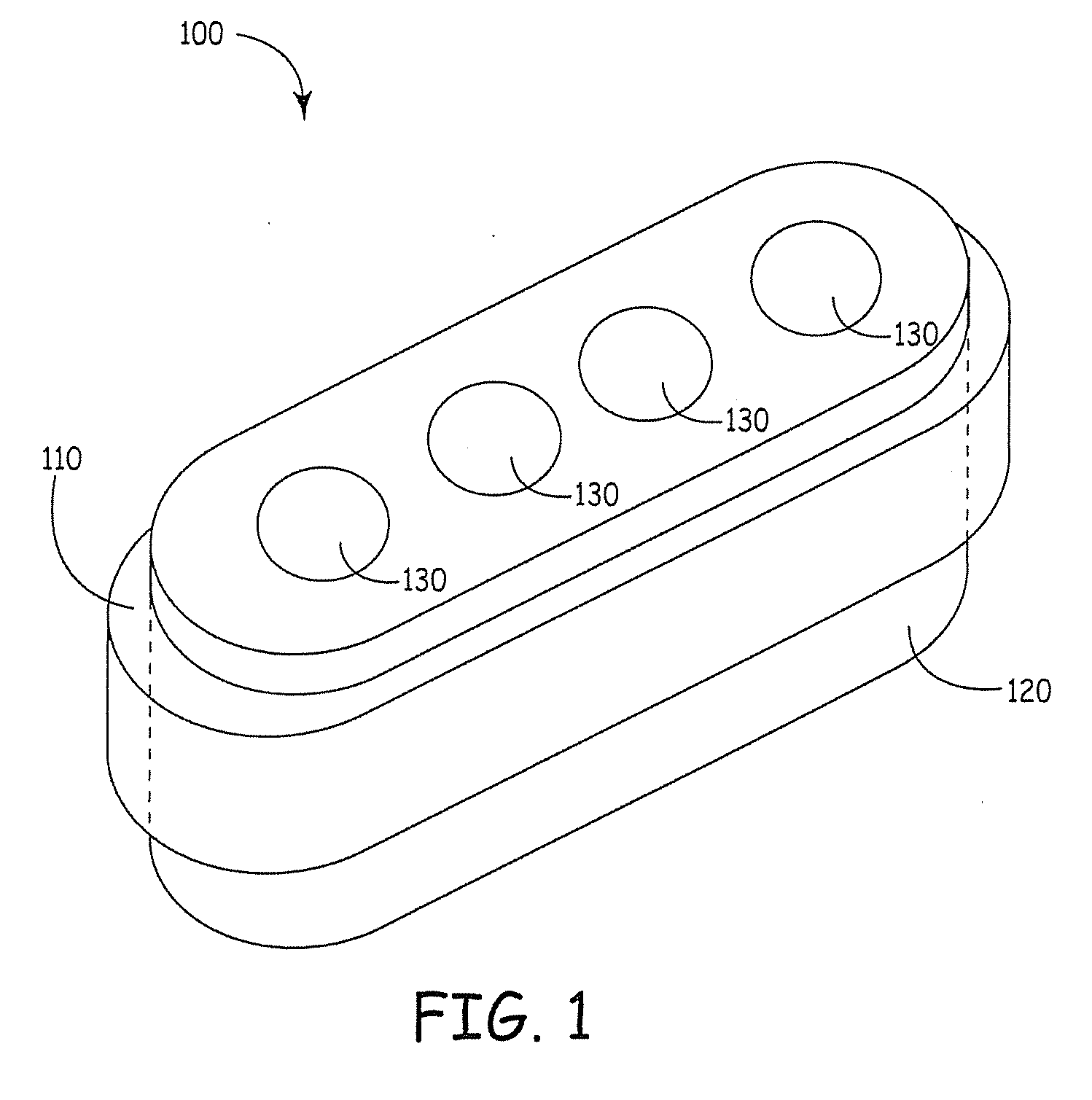
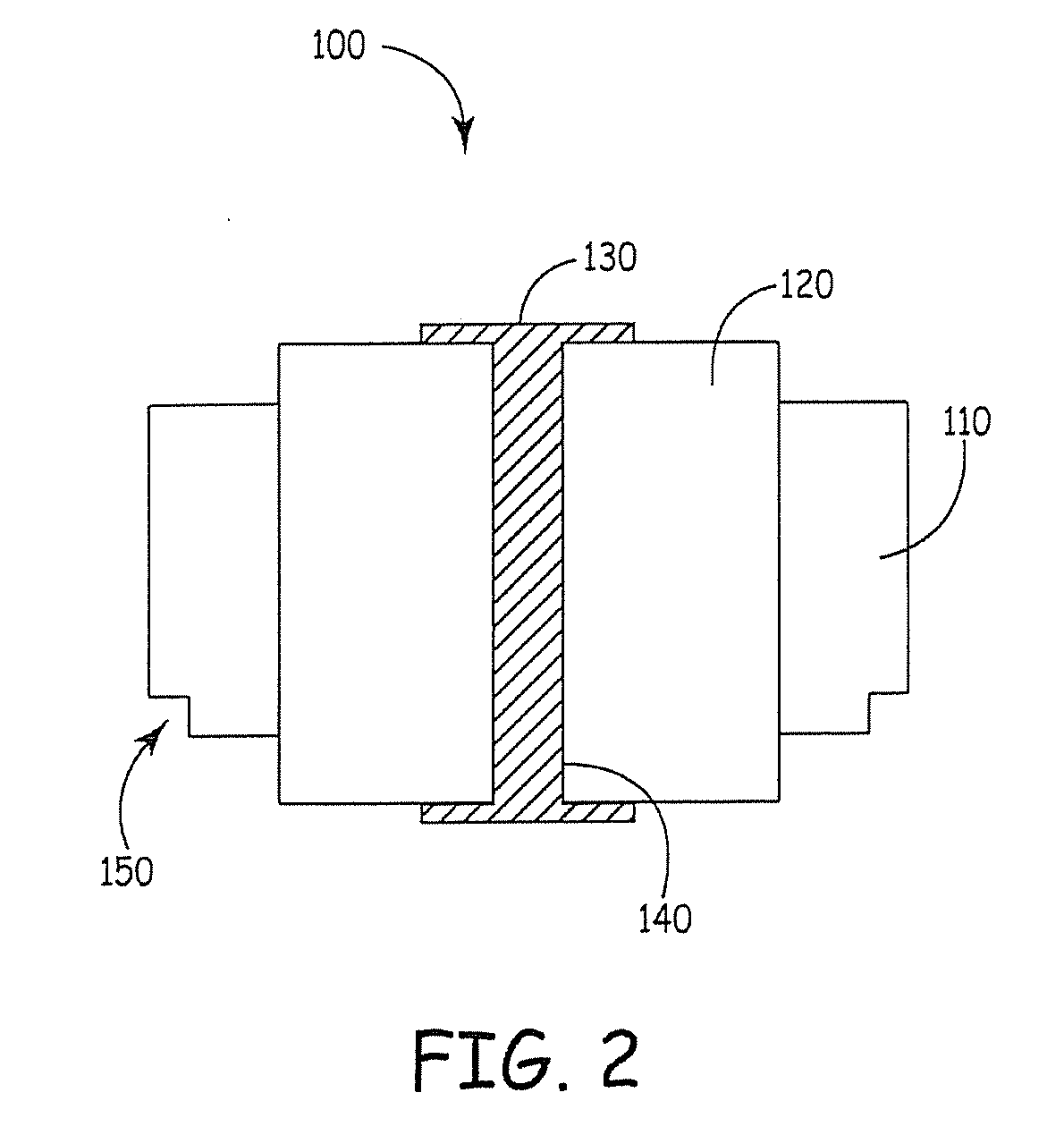
[0061]With reference to FIGS. 1 and 2, an embodiment of a feedthrough assembly 100 constructed in accordance with the present technology is shown in perspective and cross-sectional views, respectively.

[0062]The feedthrough assembly 100 includes a metal injection molded titanium ferrule 110. The ferrule110 can be over-molded about a cofired ceramic insulator 120 using a metal injection molding process. Upon sintering, densification causes the ferrule 110 and insulator 120 to bond and form a hermetic seal without any joining material, such as braze or solder, present between the ferrule 110 and insulator 120. The insulator 120 can comprise alumina (i.e., Al2O3) that can electrically isolate one or more conductive pads 130 and vias 140 comprising platinum, for example. The ferrule 110 can include a flange 150 to facilitate welding of the feedthrough assembly within an opening of an IMD cover, for example. Variations of the insulator 120 include where the electrical connections includin...

example 2

[0063]With reference to FIGS. 3A and 3B, two further embodiments of feedthrough assemblies 160, 190 constructed in accordance with the present technology are shown in cross-sectional view.

[0064]The feedthrough assemblies 160, 190 include metal injection molded titanium ferrules 180, 210 that are over-molded about insulators 170, 200 using a metal injection molding process. In such cases, the insulator is placed within at least a portion of the mold. Use of metal injection molding allows the ferrule to be molded about an insulator geometry that precludes separate molding of the ferrule followed by fitting the ferrule about the insulator. One or more features of the insulator may make it difficult or even impossible to fit a separately molded ferrule about an insulator.

[0065]As shown in FIG. 3A, an insulator 170 may have an inset portion 220 that is filled by a ferrule 180 when the ferrule 180 is over-molded about the insulator 170. As shown in FIG. 3B, an insulator 200 may have an ou...


PUM

PropertyMeasurementUnit
temperatureaaaaaaaaaa
grain sizeaaaaaaaaaa

Abstract

Feedthrough assemblies and methods of manufacturing feedthrough assemblies are provided. Methods include molding a ferrule comprising titanium using metal injection molding and positioning the ferrule about at least a portion of an insulator, the insulator comprising alumina. Methods also include overmolding a ferrule about at least a portion of an insulator using metal injection molding, the ferrule comprising titanium and the insulator comprising alumina. Sintering densifies the ferrule and provides a hermetic seal between the ferrule and insulator. The insulator may be fired or unfired prior to sintering of the ferrule.

Description

CROSS-REFERENCE TO RELATED APPLICATIONS[0001]This application claims the benefit of U.S. Provisional Application No. 61 / 238,515, filed on Aug. 31, 2009. The entire disclosure of the above application is incorporated herein by reference.INTRODUCTION[0002]The present technology relates to electrical feedthroughs and methods of fabricating feedthroughs, including feedthroughs for use with implantable medical devices.[0003]Electrical feedthroughs serve the purpose of providing an electrical circuit path extending from the interior of a hermetically sealed case or housing to an external point outside the case. Implantable medical devices (IMDs) such as implantable pulse generators (IPGs) for cardiac pacemakers, implantable cardioverter / defibrillators (ICDs), nerve, brain, organ, and muscle stimulators and implantable monitors, and the like, employ such electrical feedthroughs through their case to make electrical connections with leads, electrodes, and sensors located outside the case.[0...

Claims


Application Information

Patent Timeline
Patent Type & Authority Applications(United States)
IPC IPC(8): H01B17/30B22F7/04
CPCA61N1/3754H01B19/00B22F5/10B22F7/062B22F7/08C04B37/021C04B2237/343C04B2237/348C04B2237/365C04B2237/368C04B2237/403C04B2237/405C04B2237/406C04B2237/408C04B2237/62C22C14/00C22C19/007C22C19/03B22F3/225
Inventor REITERER, MARKUSTISCHENDORF, BRAD C.THOM, ANDREW
Owner MEDTRONIC INC
Why Eureka
Try Eureka