Electrochemical cell including a plasma source and method of operating the electrochemical cell

Inactive Publication Date: 2011-03-03
CASE WESTERN RESERVE UNIV
View PDF6 Cites 16 Cited by
  • Summary
  • Abstract
  • Description
  • Claims
  • Application Information

AI Technical Summary

Benefits of technology

[0051]These experiments are repeated for different CV concentrations, and it is found that the optimal time to obtain a maximum Raman scattering signal is approximately 20 minutes for each CV concentration. In FIG. 8(b), Raman spectra are shown for solutions with decreasing initial concentrations of CV from 10−5 to 10−10 M CV. Raman modes for CV are discernable down to a concentration of 100 μM. Some of these experiments are repeated by first preparing Ag nanoparticles, then adding the CV to the solutions, but it is found that the intensity of the scattered signals is much weaker. This indicates that the synthesis of Ag nanoparticles with the target molecule improves the interaction between the particles and the target molecules necessary for SERS enhancement.
[0052]The SERS enhancement is observed to depend on two key factors: the excitation of surface plasmons in the metal nanoparticles and the proximity of the analyte molecules to the metal surface. For a given metal material, e.g. Ag, the SERS enhancement is found to be particularly strong at the junction of two or more nanoparticles, referred to as “hot spots,” where an analyte molecule is trapped and the electromagnetic field is concentrated. Aggregates of metal nanoparticles can yield significant enhancements because of numerous and random junction sites that increase the number of these

Problems solved by technology

Applications of this technology, know as glow discharge electrolysis, remain elusive, however, because stable discharge operation of the plasma requires a vacuum environment, which restricts potential electrolytes to those with extremely low vapor pressures, such as ionic liquids or solid oxides.

Method used


Image

  • Electrochemical cell including a plasma source and method of operating the electrochemical cell
  • Electrochemical cell including a plasma source and method of operating the electrochemical cell
  • Electrochemical cell including a plasma source and method of operating the electrochemical cell

Examples


Embodiment Construction

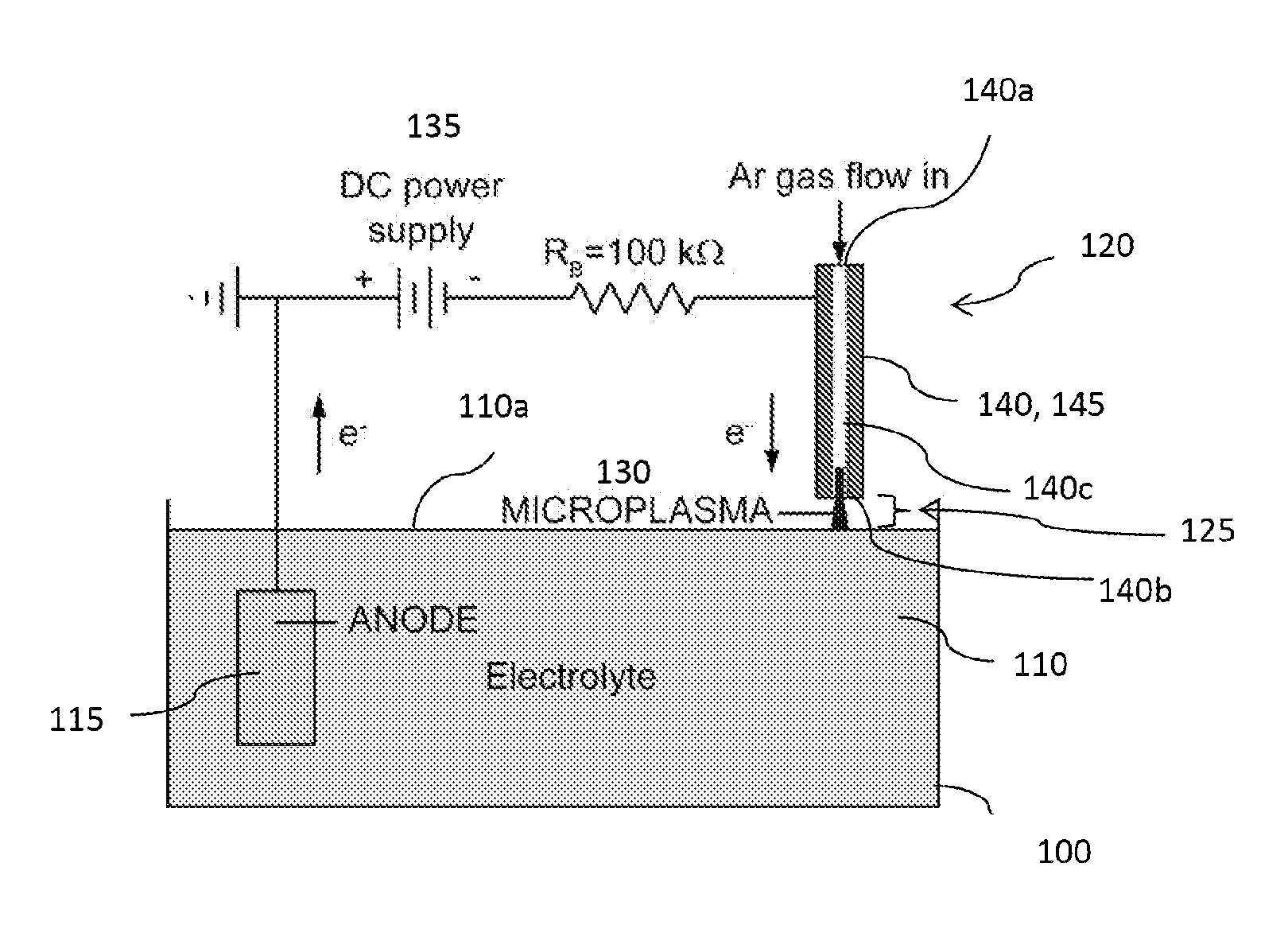
[0019]Recently, spatially confining plasmas to dimensions of 1 mm or less has led to the generation of stable glow discharges at atmospheric pressure. Microplasmas are a unique class of gaseous discharges that operate nonthermally at high pressures, in contrast to arcs. While possessing properties similar to low-pressure glows, microplasmas may be formed in a hollow cathode geometry that can result in a drastic increase in ionization processes through the oscillatory motion of electrons. As a result, microplasmas are characterized by high current densities, high-pressure operation (up to and exceeding atmospheric pressure), and relatively low gas temperatures.

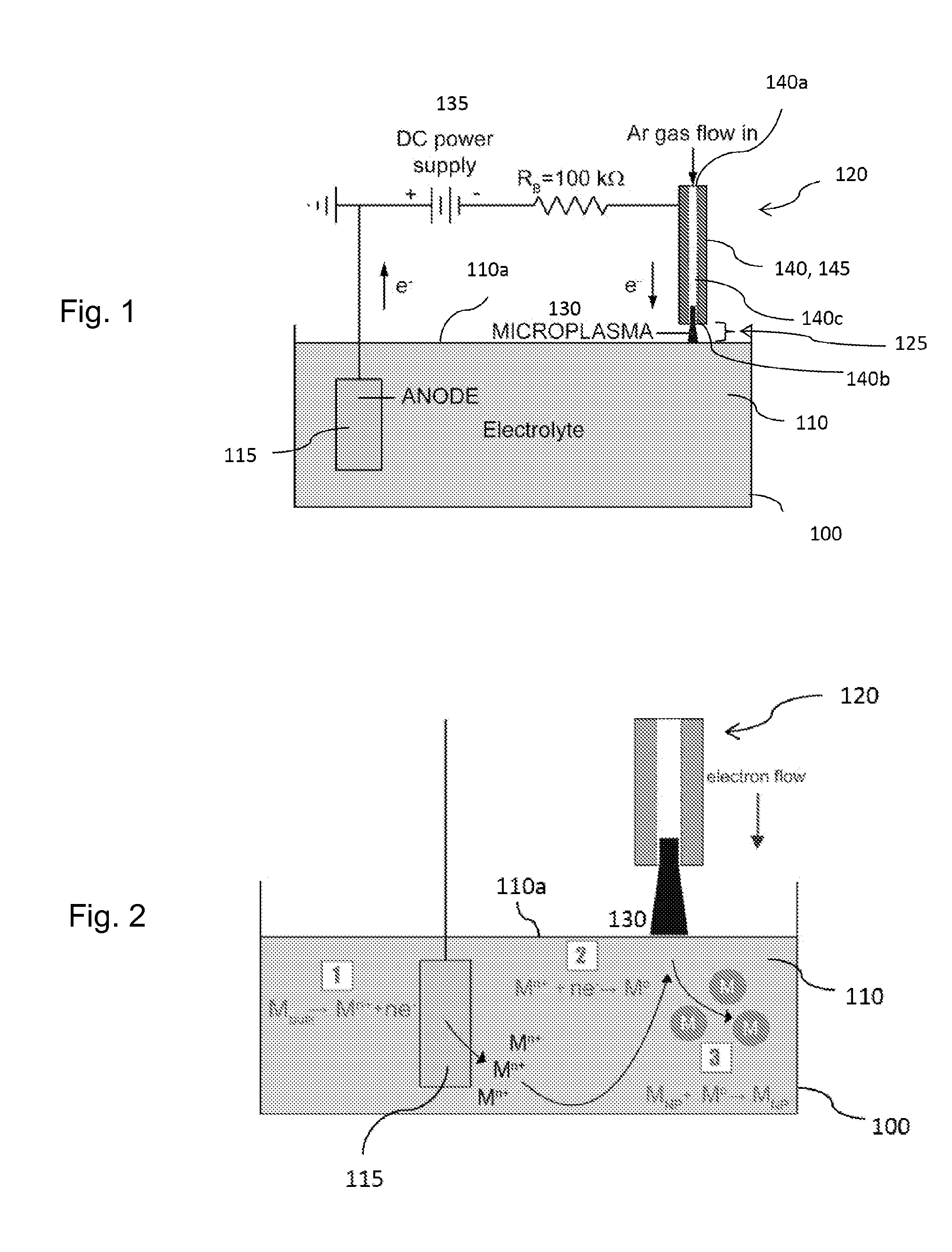
[0020]The inventor has recognized that a microplasma may be coupled with a liquid electrolyte to create a gas-liquid electrochemical cell, where the microplasma functions as a cathode. The presence of electrons and ions in the gas discharge leads to current flow through an aqueous solution which drives electrochemical reactions...


PUM

PropertyMeasurementUnit
Lengthaaaaaaaaaa
Lengthaaaaaaaaaa
Diameteraaaaaaaaaa

Abstract

An electrochemical cell includes a container at atmospheric pressure comprising a liquid electrolyte and a first electrode at least partially immersed in the electrolyte. A plasma source is spaced apart from a surface of the electrolyte by a predetermined spacing, and a plasma spans the predetermined spacing to contact the surface of the electrolyte. A method of operating the electrochemical cell entails providing a first electrode at least partially immersed in a liquid electrolyte and producing a plasma in contact with a surface of the electrolyte at atmospheric pressure. The plasma acts as a second electrode, and a current is generated through the electrolyte. Electrochemical reactions involving at least the second electrode are initiated in the electrolyte.

Description

RELATED APPLICATION[0001]The present patent document claims the benefit of the filing date under 35 U.S.C. §119(e) of Provisional U.S. Patent Application Ser. No. 61 / 274,315, filed Aug. 13, 2009, which is hereby incorporated by reference.FEDERALLY SPONSORED RESEARCH OR DEVELOPMENT[0002]The present invention was made in part with U.S. government support under grant no. CBET-0746821 awarded by the National Science Foundation. The U.S. government may have certain rights in this invention.TECHNICAL FIELD[0003]The present disclosure is related generally to electrochemical cells and more particularly to electrochemical cells that utilize a plasma as an electrode.BACKGROUND[0004]Plasmas are gaseous discharges widely used to modify the surface properties of materials. Plasma-based surface processes, such as etching and deposition of thin films, are vitally important to the manufacturing of integrated circuits (ICs) in the electronics industry. Typical plasmas (also known as “glow discharges...

Claims


Application Information

Patent Timeline
IPC IPC(8): C25C1/00C25C7/02C25C7/06B82Y40/00
CPCB22F9/14B22F2998/00B22F2999/00B82Y30/00B82Y40/00C25C1/00C25C7/06B22F1/0018B22F2202/13B22F1/054
Inventor SANKARAN, R. MOHAN
Owner CASE WESTERN RESERVE UNIV
Why Eureka
Try Eureka