
Edge lighting control

a technology for controlling edge lighting and display units, applied in the field of electronic devices, can solve the problems of not being able the mechanical bezel around the tv set is typically not decorative, and the clear bezel is still inability to match the decor of the room, so as to improve the product differentiation, enhance the user experience, and improve the room decor

Inactive Publication Date: 2011-03-03
SONY CORP +1
View PDF11 Cites 55 Cited by
  • Summary
  • Abstract
  • Description
  • Claims
  • Application Information

AI Technical Summary

Benefits of technology

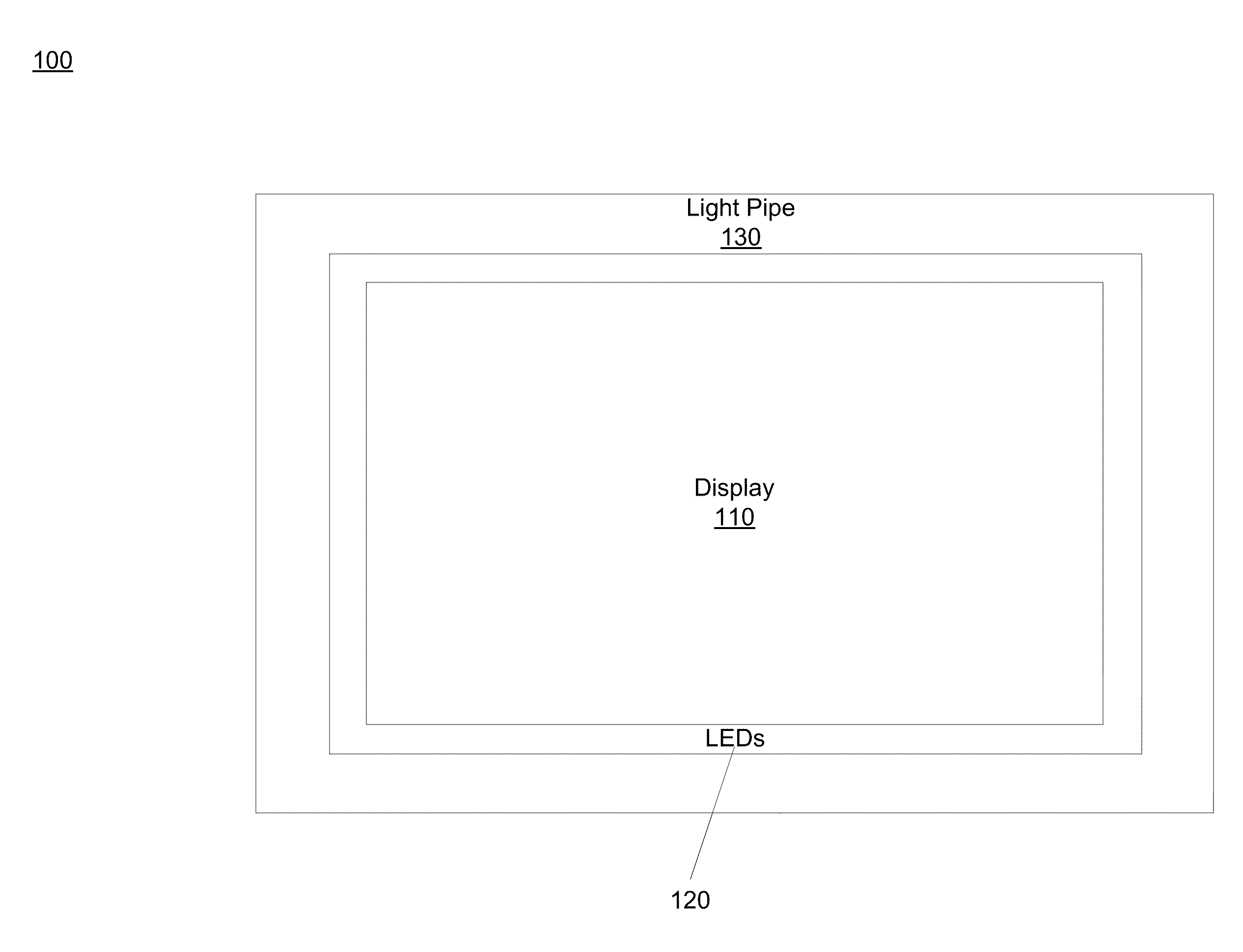
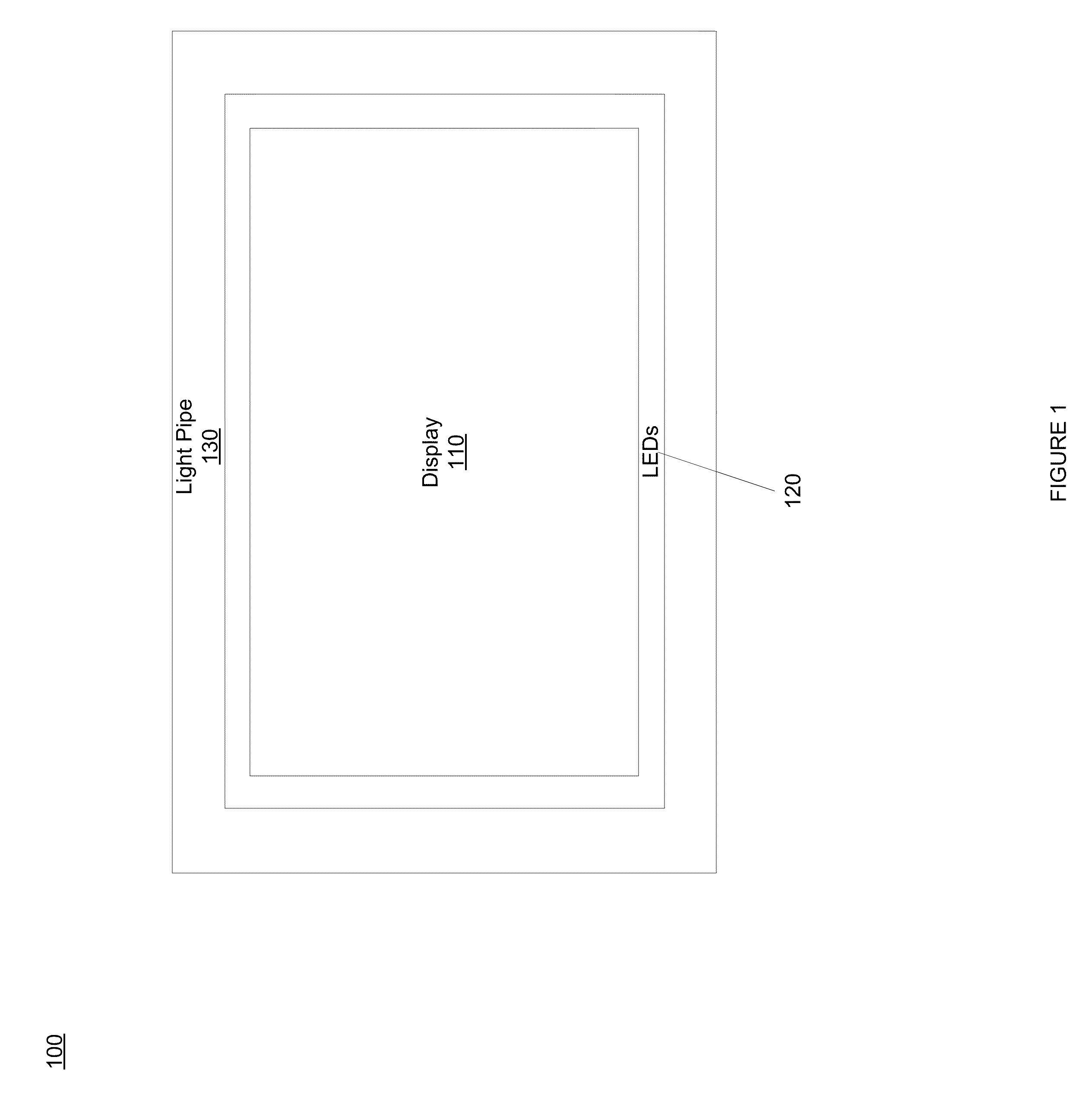
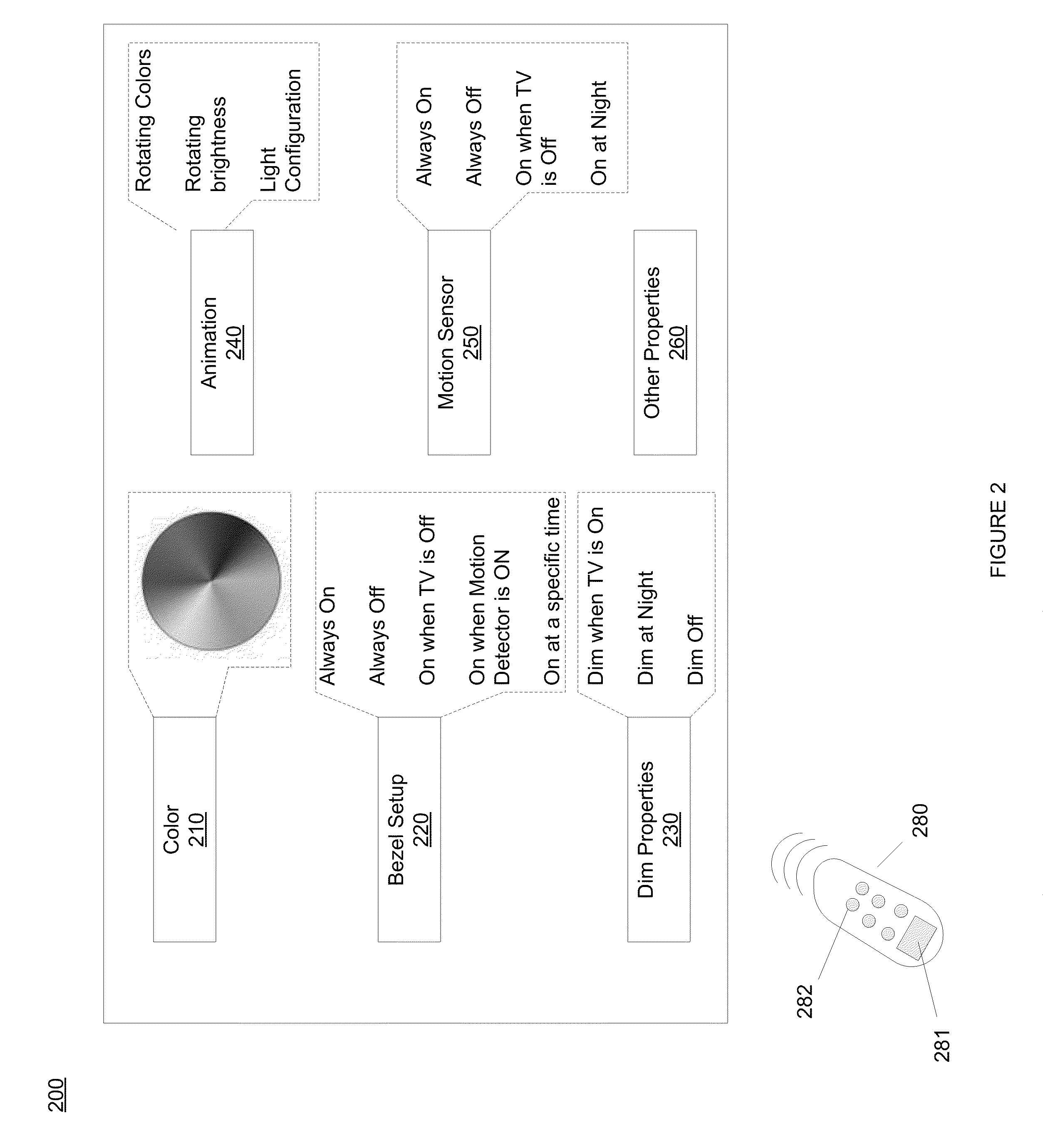
[0010]Accordingly, the operation of edge lighting of a television set may be controlled by a user. The operation of the edge lighting of the television set may be altered responsive to user preferences, e.g., based on the room decor. As such, a television set becomes not only functional but rather decorative and enhances the user experience by improving the room decor. Edge lighting also improves product differentiation.

Problems solved by technology

Unfortunately, the mechanical bezel around the television set is typically not decorative.
However, the clear bezel is still incapable of being matched with the decor of the room, e.g., paint colors, chairs, tables, etc.
Accordingly, television sets with clear bezels may still look not decorative, thereby lacking harmony with their surrounding decor.
Unfortunately, the bezel does not render a color when the television is turned off.
Thus, the conventional system that changes the color of the bezel is also not decorative when the television set is turned off.
Moreover, the color rendered by the bezel or color operation itself are neither user selectable nor user controllable.

Method used


Image

  • Edge lighting control
  • Edge lighting control
  • Edge lighting control

Examples


Embodiment Construction

[0016]Reference will now be made in detail to embodiments of the present invention, examples of which are illustrated in the accompanying drawings. While the invention will be described in conjunction with these embodiments, it will be understood that they are not intended to limit the invention to these embodiments. On the contrary, the invention is intended to cover alternatives, modifications and equivalents, which may be included within the spirit and scope of the invention as defined by the appended claims. Furthermore, in the following detailed description of the present invention, numerous specific details are set forth in order to provide a thorough understanding of the present invention. However, it will be evident to one of ordinary skill in the art that the present invention may be practiced without these specific details. In other instances, well known methods, procedures, components, and circuits have not been described in detail as not to unnecessarily obscure aspects ...


PUM


Abstract

An edge lighting control for a television set. A television set includes a display, an edge lighting bezel surrounding the display, a processor, and a memory component. The edge lighting bezel is operable to output light and its operation is user controllable, e.g., interaction between a GUI and a remote control. The processor controls the operation of the edge lighting bezel, e.g., dimming the output light and its color pattern, in response to user input. The memory component stores instructions and data for controlling the operation of the edge lighting bezel when processed by the processor. The edge lighting bezel may include a ring of light emitting diodes (LEDs) surrounding the display and a light pipe surrounding the ring. The ring is operable to emit light responsive to the user input and the light pipe is operable to transmit light emitted from the ring.

Description

TECHNICAL FIELD[0001]Embodiments of the present invention relate to the field of electronics. More particularly, embodiments of the present invention relate to controlling edge lighting of a display unit.BACKGROUND ART[0002]Generally, displays, e.g., television sets, are not considered as decorative items but rather functional. However, the appearance of a television set is becoming more important in light of new technologies and new uses and locations of television sets. For example, television sets are being used to display photo albums. Unfortunately, the mechanical bezel around the television set is typically not decorative.[0003]Some have developed clear bezels with clear decorative edges to improve the appearance of television sets. However, the clear bezel is still incapable of being matched with the decor of the room, e.g., paint colors, chairs, tables, etc. Accordingly, television sets with clear bezels may still look not decorative, thereby lacking harmony with their surro...

Claims


Application Information

Patent Timeline
Patent Type & Authority Applications(United States)
IPC IPC(8): H04N5/66
CPCH04N5/64H05B33/0857H05B37/0227G09G2320/08G09G5/003G09G2310/0232H05B37/029H05B45/20H05B47/105H05B47/115H05B47/155H05B47/175Y02B20/40
Inventor HARDACKER, ROBERTCALDERON, RAFAELRICHMAN, STEVEN
Owner SONY CORP
Learn More