Electrolytic capacitor

a technology of electrolytic capacitors and capacitors, applied in the field of electrolytic capacitors, can solve the problems of multi-terminal structure of conventional electrolytic capacitors, and achieve the effects of facilitating registration in manufacturing, and maintaining characteristics of electrolytic capacitors

Active Publication Date: 2011-03-03
SAGA SANYO IND +1
View PDF1 Cites 7 Cited by
  • Summary
  • Abstract
  • Description
  • Claims
  • Application Information

AI Technical Summary

Benefits of technology

[0050]According to the fifth electrolytic capacitor of the present invention, at least one of the first anode lead tab terminal and the second anode lead tab terminal is formed such that the position in the radial direction of the anode lead is different from the position in the radial direction of the anode connection portion in a state that the anode foil is wound up. Thus, at least one of shifting toward the outer circumference of the position in the radial direction of the anode lead of the first anode lead tab terminal and shifting toward the inner circumference of the position in the radial direction of the anode lead of the second anode lead tab terminal can be made. Therefore, even when the position in the radial direction of the anode connection portion of the first anode lead tab terminal is arranged on the inner circumferential side relative to the position in the radial direction of the anode connection portion of the second anode lead tab terminal, the position in the radial direction of the anode lead of the first anode lead tab terminal and the position in the radial direction of the lead of the second anode lead tab terminal can be brought closer to each other. Therefore, since the lead of the first anode lead tab terminal can be arranged at a position corresponding to a vertex of a substantially equilateral triangle, position displacement of the anode lead tab terminal can be avoided. In addition, since substantially regular pitches between the three anode (cathode) leads of the first and second anode lead tab terminals and the cathode lead tab terminal are achieved, ESL becomes lower and characteristics as an electrolytic capacitor can be maintained.
[0051]According to the sixth electrolytic capacitor of the present invention, the three lead tab terminals include such a lead tab terminal that a lead is arranged at a position in the radial direction the same as that of the connection portion and such a lead tab terminal that a lead is arranged at a position shifted in the radial direction with respect to the connection portion, in a state that the anode foil and the cathode foil are wound. Thus, registration of the positions in the radial direction of the leads of the lead tab terminals can be achieved. Consequently, registration in manufacturing is facilitated and characteristics as an electrolytic capacitor can be maintained.
[0052]According to the seventh electrolytic capacitor of the present invention, the three lead tab terminals include such a lead tab terminal that a lead is arranged at a position shifted radially outward with respect to the connection portion and such a lead tab terminal that a lead is arranged at a position shifted radially inward with respect to the connection portion, in a state that the anode foil and the cathode foil are wound. Thus, registration of the positions in the radial direction of the leads of the lead tab terminals can be achieved. Consequently, registration in manufacturing is facilitated and characteristics as an electrolytic capacitor can be maintained.

Problems solved by technology

The inventors, however, have found that a conventional electrolytic capacitor having a multi-terminal structure suffers the following problems.

Method used


Image

  • Electrolytic capacitor
  • Electrolytic capacitor
  • Electrolytic capacitor

Examples


first embodiment

[0119]Here, an electrolytic capacitor in which a both-side pressed terminal is applied as a first anode (cathode) lead tab terminal and a one-side pressed terminal is applied as a second anode (cathode) lead tab terminal will be described.

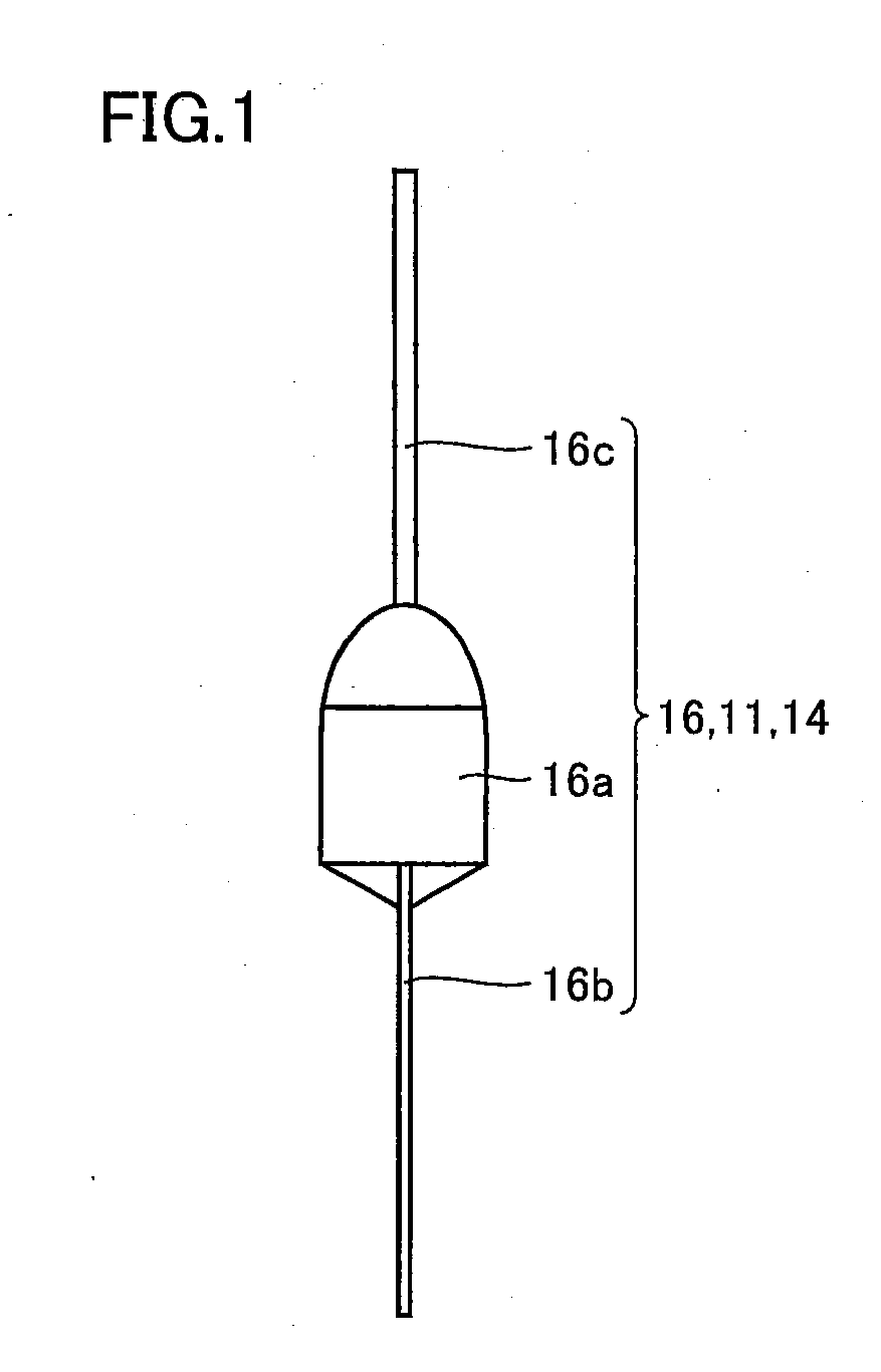
[0120]As shown in FIG. 1, a both-side pressed terminal 16 is molded substantially symmetrical with respect to a lead 16c by using two identical molds, and a columnar boss portion 16a, a plate-shaped connection portion 16b connected to an anode (cathode) foil, and columnar lead 16c serving as an anode (cathode) terminal are molded. Lead 16c is provided on one-end side of boss portion 16a, and connection portion 16b is provided on the other end side of boss portion 16a. In FIG. 1, plate-shaped connection portion 16b is arranged in a direction perpendicular to the sheet surface.

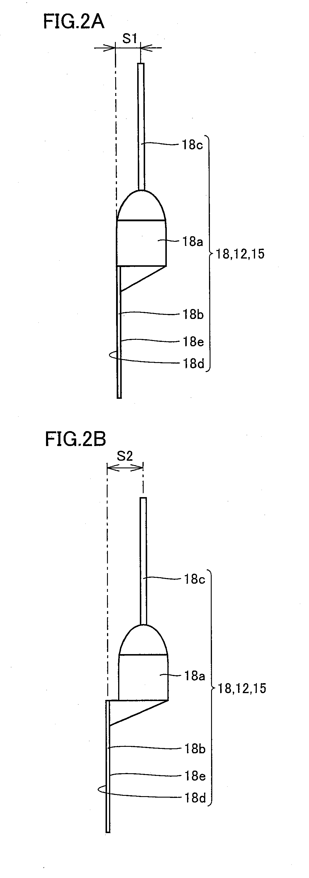
[0121]Meanwhile, as shown in FIGS. 2A and 2B, a one-side pressed terminal 18 is molded asymmetrical with respect to lead 16c by mainly using one mold of two identical molds. FI...

second embodiment

[0140]Here, an electrolytic capacitor in which a one-side pressed terminal is applied as the first anode (cathode) lead tab terminal and a both-side pressed terminal is applied as the second anode (cathode) lead tab terminal will be described.

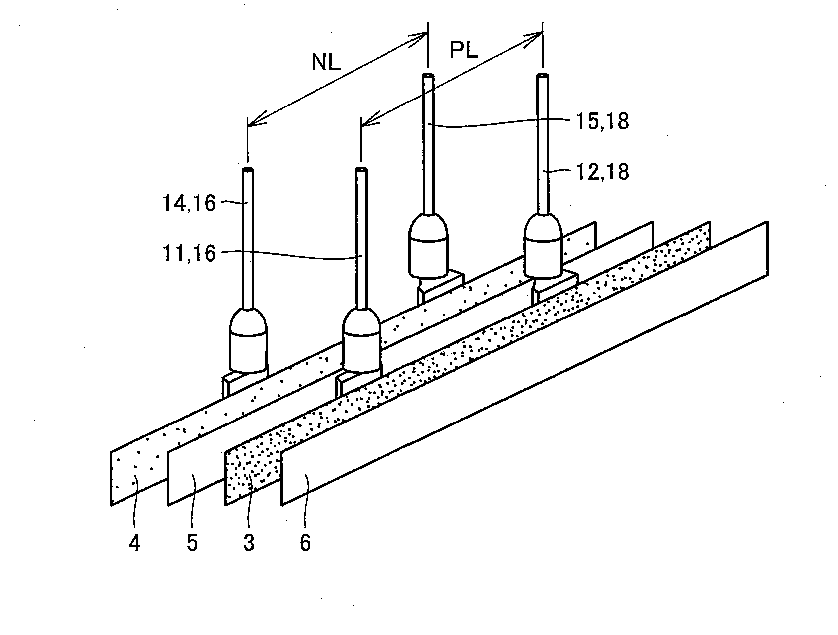
[0141]Initially, as shown in FIG. 13, at prescribed positions in a longitudinal direction of anode foil 3, one-side pressed terminal 18 is connected as first anode lead tab terminal 11 and both-side pressed terminal 16 is connected as second anode lead tab terminal 12. In addition, at prescribed positions in a longitudinal direction of cathode foil 4, one-side pressed terminal 18 is connected as first cathode lead tab terminal 14 and both-side pressed terminal 16 is connected as second cathode lead tab terminal 15.

[0142]Here, as in the electrolytic capacitor described previously, first anode lead tab terminal 11 is connected to a portion of anode foil 3 arranged at a prescribed distance (a first distance) from the one-end side of anode foil 3, ...

example i

[0167]The inventors fabricated 500 electrolytic capacitors in which a both-side pressed terminal was applied as the first anode (cathode) lead tab terminal and a one-side pressed terminal was applied as the second anode (cathode) lead tab terminal (the first embodiment) and 500 electrolytic capacitors in which a one-side pressed terminal was applied as the first anode (cathode) lead tab terminal and a both-side pressed terminal was applied as the second anode (cathode) lead tab terminal (the second embodiment), and evaluated positions of four completed anode (cathode) lead tab terminals (leads) (arrangement geometry).

[0168]It is noted that a specific method of manufacturing an electrolytic capacitor is as described in the first embodiment and the second embodiment above and a diameter was set to 8.0 mm. In addition, 500 electrolytic capacitors in which a both-side pressed terminal was applied as the first (second) anode (cathode) lead tab terminal were fabricated as Comparative Exam...


PUM


Abstract

A both-side pressed terminal is connected as a first anode (cathode) lead tab terminal to an anode (a cathode) foil. A first connection surface of a connection portion of a one-side pressed terminal as a second anode (cathode) lead tab terminal is connected to an inner circumferential surface of the anode (cathode) foil. A position in a radial direction of a lead of the second anode (cathode) lead tab terminal is shifted inward to be in registration with a position in a radial direction of a lead of the first anode (cathode) lead tab terminal. Thus, an electrolytic capacitor free from position displacement of an anode (a cathode) lead tab terminal while maintaining characteristics as an electrolytic capacitor can be obtained.

Description

[0001]This nonprovisional application is based on Japanese Patent Application No. 2009-199524, Japanese Patent Application No. 2009-199525 and Japanese Patent Application No. 2009-199526 filed with the Japan Patent Office on Aug. 31, 2009, the entire contents of which are hereby incorporated by reference.BACKGROUND OF THE INVENTION[0002]1. Field of the Invention[0003]The present invention relates to an electrolytic capacitor, and particularly to an electrolytic capacitor formed by winding an anode foil, a cathode foil and the like.[0004]2. Description of the Background Art[0005]An electrolytic capacitor formed by winding up an anode foil and a cathode foil with separator paper being interposed represents one form of an electrolytic capacitor.[0006]Here, a method of manufacturing an electrolytic capacitor having a two-terminal (one anode terminal and one cathode terminal) structure representing such a wound-type electrolytic capacitor will now be described. Initially, as shown in FIG...

Claims


Application Information

Patent Timeline
Patent Type & Authority Applications(United States)
IPC IPC(8): H01G9/02
CPCH01G9/04H01G9/012
Inventor FUJIMOTO, KAZUMASA
Owner SAGA SANYO IND
Why Eureka
Try Eureka