Solid Electrolytic Capacitor

a solid electrolytic capacitor and capacitor technology, applied in the direction of liquid electrolytic capacitors, fixed capacitors, fixed capacitor details, etc., can solve the problems of insufficient enhancement of high frequency characteristics and difficulty in reducing the impedance in ultra high frequency ranges, and achieve the effect of enhancing high frequency characteristics by reducing esr and esl

Inactive Publication Date: 2009-01-15
ROHM CO LTD
View PDF23 Cites 12 Cited by
  • Summary
  • Abstract
  • Description
  • Claims
  • Application Information

AI Technical Summary

Benefits of technology

[0011]With such a structure, as compared with a structure in which the anode wires extend into the porous sintered body in the same direction, the maximum of the distances between each portion of the cathode and the anode wires (hereinafter referred to as “maximum distance”) can be reduced. When the maximum distance is reduced, the resistance and the inductance between the cathode and the anode terminals can be reduced. Therefore, the ESR and ESL of the solid electrolytic capacitor can be reduced, which leads to the enhancement of the high frequency characteristics.
[0034]Preferably, a plurality of porous sintered bodies are provided, and the porous sintered bodies are arranged side by side in a direction crossing the thickness direction of the porous sintered bodies. With such a structure, each of the anode terminals provided at each of the porous sintered body can be positioned close to the substrate on which the solid electrolytic capacitor is mounted. When the distance between each of the anode terminals and the substrate is reduced, the impedance for AC of a high frequency band can be reduced, which is advantageous for reducing the ESL.

Problems solved by technology

Therefore, as the capacitance is increased, decreasing of the impedance in an ultra high frequency range becomes more difficult.
In such a case, the ESR and the ESL cannot be decreased, so that the high frequency characteristics cannot be sufficiently enhanced.

Method used


Image

  • Solid Electrolytic Capacitor
  • Solid Electrolytic Capacitor
  • Solid Electrolytic Capacitor

Examples


Embodiment Construction

[0060]Preferred embodiments of the present invention will be described below in detail with reference to the accompanying drawings.

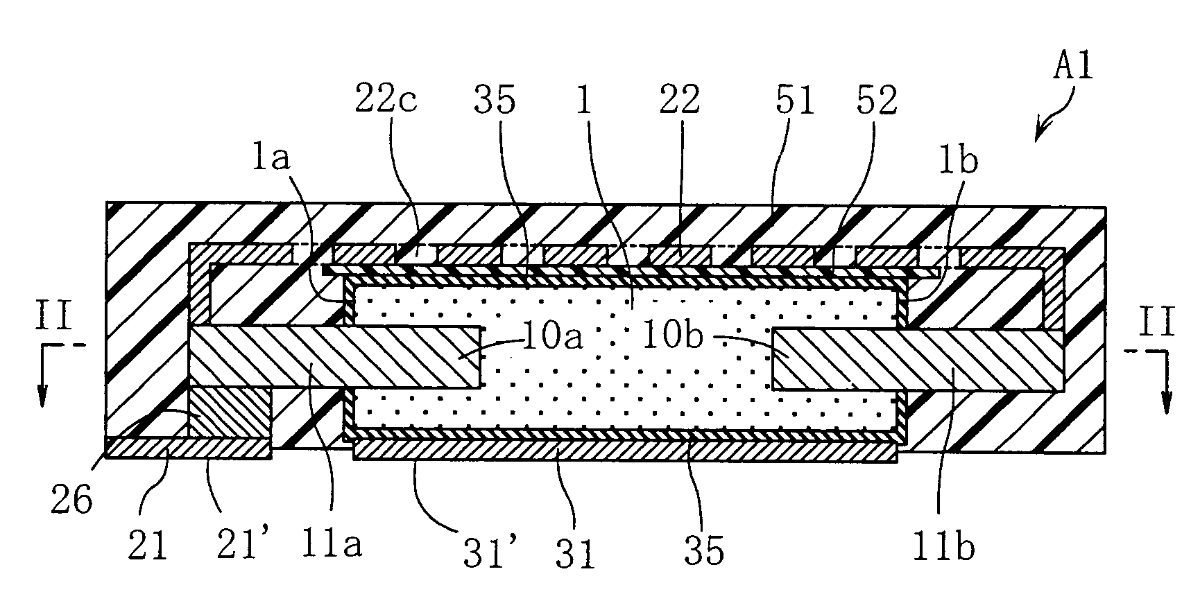
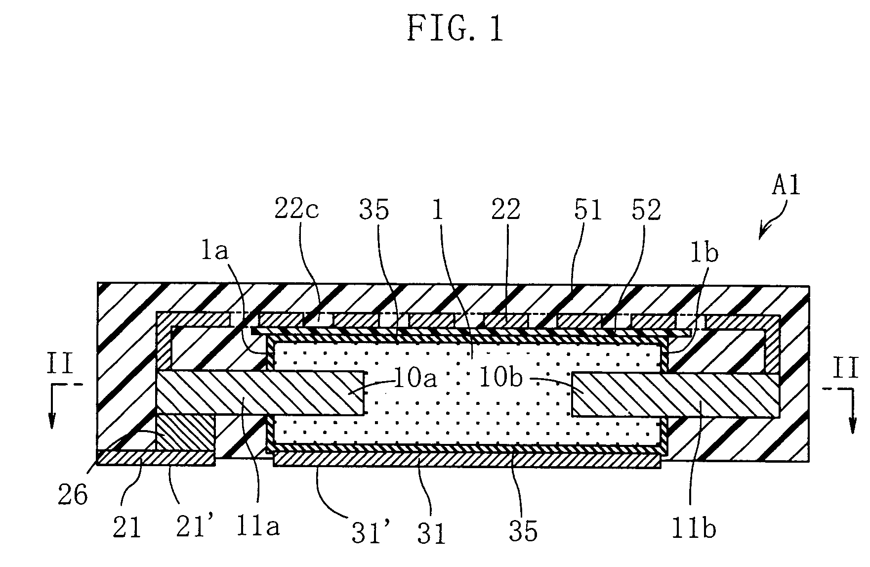
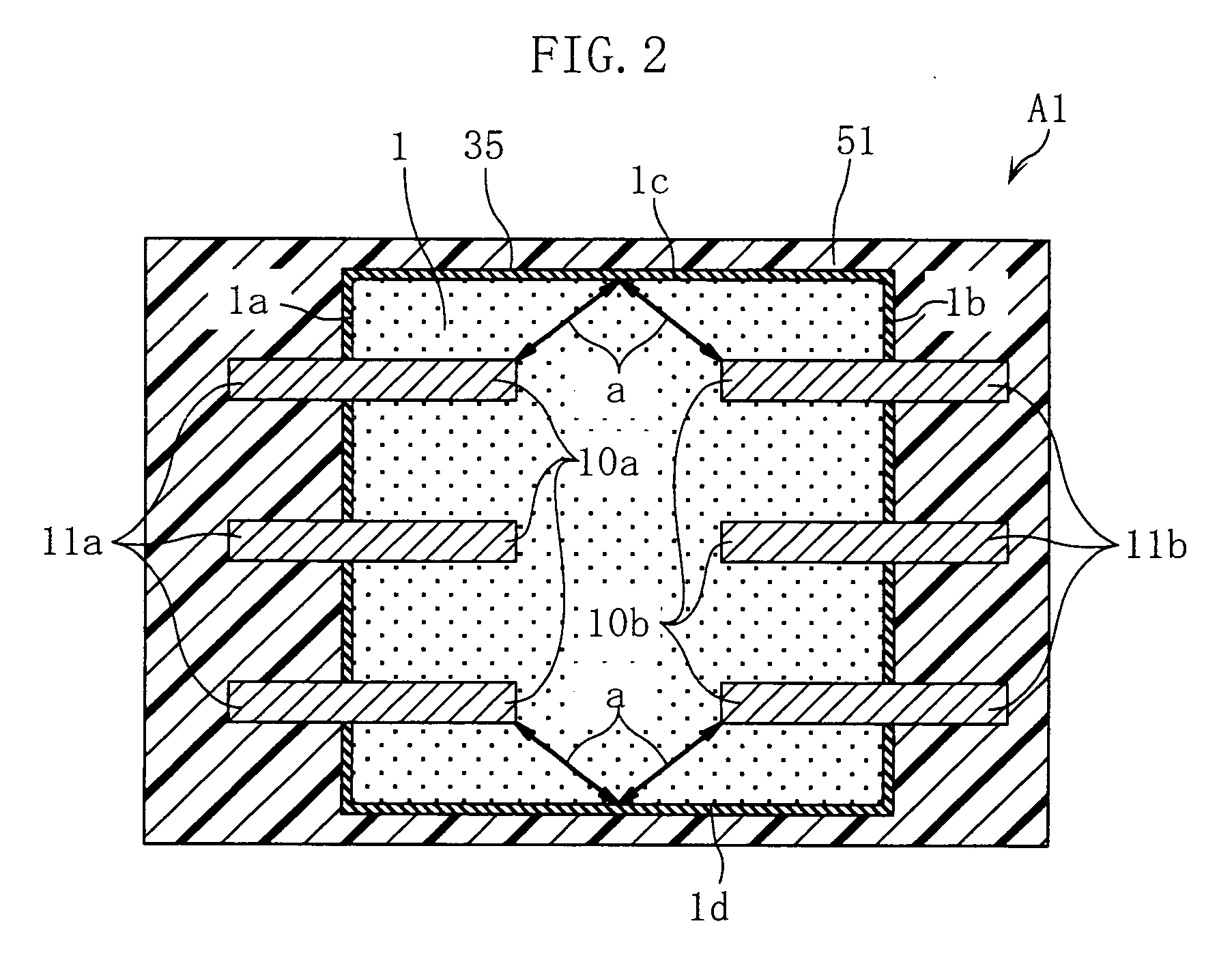
[0061]FIGS. 1-3 show an example of solid electrolytic capacitor according to the present invention. The solid electrolytic capacitor A1 in this embodiment includes a porous sintered body 1, three first anode wires 10a, three second anode wires 10b, a metal cover 22, and sealing resin 51 covering the porous sintered body 1. In FIG. 3, the sealing resin 51 is omitted.

[0062]The porous sintered body 1 is in the form of a rectangular plate and formed by compacting niobium powder which is valve metal powder and then sintering the compacted body. The porous sintered body 1 may be made of any valve metal. For instance, tantalum may be used instead of niobium. Niobium is superior in flame retardancy to tantalum. Since the porous sintered body 1 produces heat in using the solid electrolytic capacitor A1, niobium is preferable as the material of the porous sintered...


PUM

PropertyMeasurementUnit
conductiveaaaaaaaaaa
insulatingaaaaaaaaaa
circuit currentaaaaaaaaaa

Abstract

A solid electrolytic capacitor (A1) includes a first and a second anode terminals (11a, 11b) projecting in different directions from each other. Preferably, a metal cover (22) for electrically connecting the anode terminals (11a, 11b) to each other is provided. With such an arrangement, the ESR and the ESL can be reduced, and the high frequency characteristics can be enhanced.

Description

TECHNICAL FIELD[0001]The present invention relates to a solid electrolytic capacitor which utilizes a porous sintered body of valve metal.BACKGROUND ART[0002]A solid electrolytic capacitor is used for canceling a noise generated from an electronic device such as a CPU, for example. Operation speed of CPUs has been improved to a large degree. With respect to a solid electrolytic capacitor, therefore, excellent noise cancellation performance for a wide frequency band including a high frequency band is demanded. A solid electrolytic capacitor is used also for assisting a power supply system for supplying power to an electronic device. In accordance with an increase in clock speed and digitalization of electronic devices, a solid electrolytic capacitor is demanded which is capable of realizing high power supply at high speed. To realize the high power supply, it is necessary that the capacitance is large and that the heat generation at the porous body is reduced.[0003]The frequency char...

Claims


Application Information

Patent Timeline
Patent Type & Authority Applications(United States)
IPC IPC(8): H01G9/052H01G9/012H01G9/14
CPCH01G9/012H01G9/14H01G9/10H01G9/15
Inventor KURIYAMA, CHOJIRO
Owner ROHM CO LTD
Why Eureka
Try Eureka