Solid electrolytic capacitor

a solid electrolytic capacitor and capacitor technology, applied in the direction of electrolytic capacitors, liquid electrolytic capacitors, capacitors, etc., can solve the problems of difficulty in achieving uniform density of manufactured sintered bodies, and difficulty in forming dielectric layers, etc., to achieve the effect of reducing static capacitance of solid electrolytic capacitors, reducing contact pressure, and increasing electrical resistance and inductan

Inactive Publication Date: 2007-08-02
ROHM CO LTD
View PDF12 Cites 12 Cited by
  • Summary
  • Abstract
  • Description
  • Claims
  • Application Information

AI Technical Summary

Benefits of technology

[0071] Hereunder, advantageous effects of the solid electrolytic capacitor A1 will be described.
[0072] Since the solid electrolytic capacitor A1 includes two porous sintered bodies 1, the total volume of the porous sintered bodies 1 included in the solid electrolytic capacitor A1 can be easily increased. When a single entity of the porous sintered body 1 is excessively large in dimensions unlike this embodiment, the porous compact to constitute the porous sintered body has to be also large, in which case the density may become uneven. When the density of the porous compact is uneven, sufficient contact pressure may not be ensured between the porous compact and the anode wire 10a, 10b inserted into the compact. Sintering such porous compact only results in higher electrical resistance and inductance at connection points between the porous sintered bodes 1 and the anode wires 10a, 10b, thus failing in properly reducing the ESR and ESL of the solid electrolytic capacitor A1. Also, for example when the density in the vicinity of the surface of the porous sintered body 1 becomes unduly high and thereby inhibits proper formation of fine pores on the surface, the porous sintered body 1 cannot be sufficiently impregnated with a predetermined solution for forming the dielectric layer 13 and the solid electrolytic layer 36. Under such situation the dielectric layer 13 and the solid electrolytic layer 36 cannot be properly formed on the porous sintered body 1, which may lead to a drawback such as reduction in static capacitance of the solid electrolytic capacitor A1 or an increase in leak current. According to this embodiment, while each of the porous sintered bodies 1 is formed in such a size that barely incurs uneven density, the total volume of the porous sintered bodies 1 included in the solid electrolytic capacitor A1 can be increased. Accordingly, the capacitance of the solid electrolytic capacitor A1 can be increased while preventing the disadvantages such as disturbance against reduction in ESR and ESL of the solid electrolytic capacitor A1 and an increase in leak current. Naturally it is possible to employ just one sintered body to obtain a capacitor that performs a desired function, and the present invention does not exclude such a case.
[0073] The two porous sintered bodies 1 are low in height, which is advantageous for making the solid electrolytic capacitor A1 thinner. When the solid electrolytic capacitor A1 is mounted for example on a substrate of an electronic apparatus, the solid electrolytic capacitor A1 can be kept from excessively protruding upward from the substrate, which facilitates making the electronic apparatus thinner.
[0074] In the respective porous sintered body 1, the distance between each anode wire 10a, 10b and the conductive layer 35 can be shortened. Therefore, the electrical path in each porous sintered body 1 can be shortened, which facilitates reducing the resistance and inductance.
[0075] Also, the distance between the internal anode terminals 11a, 11b and the external anode terminals 21a, 21b can be shortened, as compared with the case where, unlike this embodiment, for example two porous sintered bodies are vertically stacked. Such structure is advantageous in reducing the resistance and inductance of the electrical path between the internal anode terminals 11a, 11b and the external anode terminals 21a, 21b. Especially, the portion of the electrical path constituted of the conductor 23a, 23b is vertically erected, on both sides of which the running direction of the current is changed. Such portion has, the longer it is, the greater inductance against an alternating current in such a high-frequency region as including harmonics, as compared with a peripheral portion. In this embodiment, since the distance between the internal anode terminals 11a, 11b and the external anode terminals 21a, 21b is shortened, the conductors 23a, 23b are low in height. Accordingly, the erected portion has low inductance, which enables reducing the ESL of the solid electrolytic capacitor A1 as a whole, and thereby improving the noise removal characteristic in the high-frequency region, as well as the response speed in supplying the power.
[0076] The input / output anode wires 10a, 10b are spaced from each other across the porous sintered body 1, instead of being concentrated in a portion of the porous sintered body 1. Providing numerous anode wire 10a, 10b on one of the lateral faces of the porous sintered body 1 may lead to insufficient strength of the porous sintered body 1 thus incurring a crack or excessive heat generation at a connection point with the anode wires 10a, 10b. This embodiment prevents such drawbacks, thereby allowing the solid electrolytic capacitor A1 to perform its function to the fullest extent.

Problems solved by technology

However, the larger the porous sintered body 90 is, the more difficult it becomes to attain a uniform density for the manufactured sintered body.
Unfavorably, nonuniform density leads to difficulty in forming a dielectric layer (not shown) or a solid electrolytic layer (not shown) in the pores of the sintered body 90.
Another drawback is that the porous sintered body 90 and the anode wire 91 fail to be securely bonded to each other.
A device such as a CPU with a high-speed clock generates a high-frequency noise containing harmonics components.

Method used


Image

  • Solid electrolytic capacitor
  • Solid electrolytic capacitor
  • Solid electrolytic capacitor

Examples


first embodiment

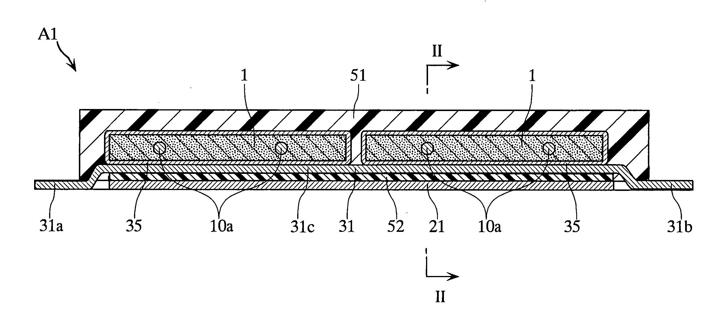
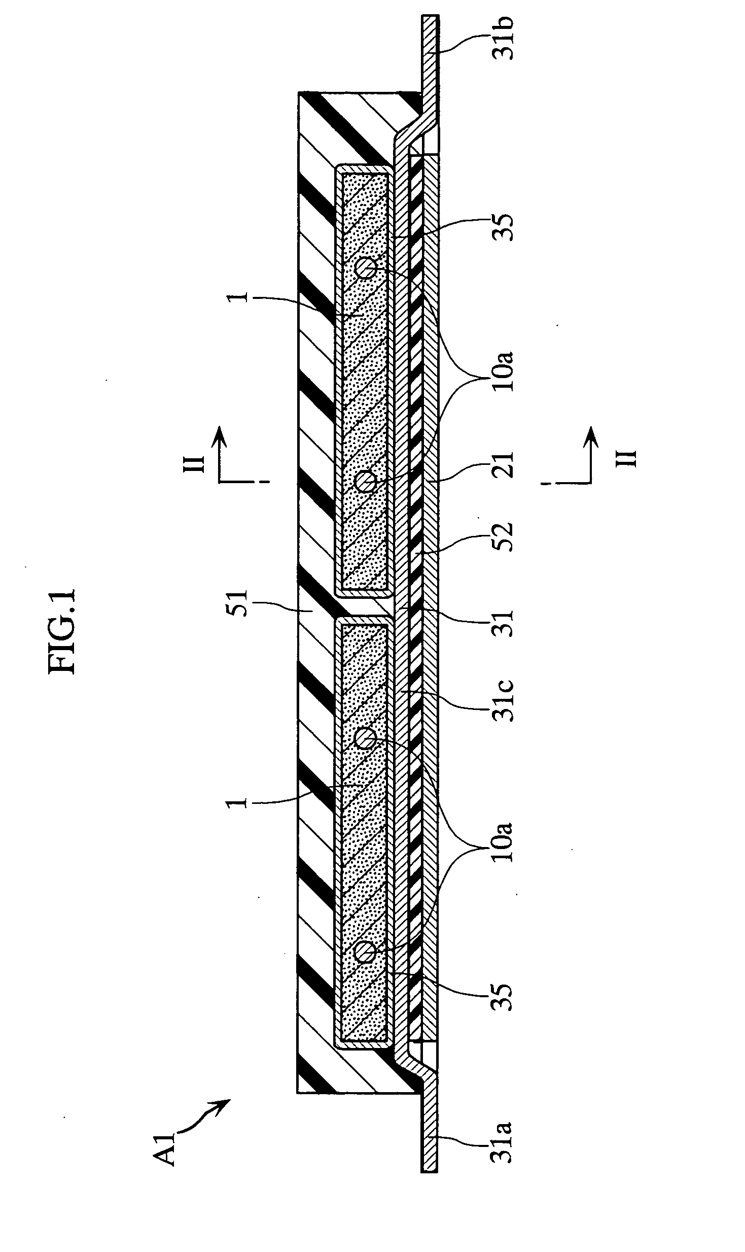
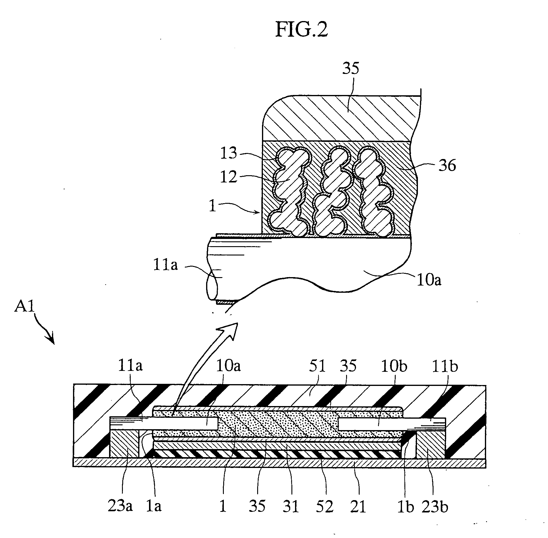
[0062] FIGS. 1 to 4 depict a solid electrolytic capacitor according to the present invention. The solid electrolytic capacitor A1 includes two porous sintered bodies 1 and eight anode wires 10a, 10b. The capacitor A1 includes input / output external anode terminals 21a, 21b and input / output external cathode terminals 31a, 31b, thus being constituted as a so-called four-terminal type capacitor. The two sintered bodies 1 and the eight wires 10a, 10b are collectively covered with an encapsulating resin 51. In FIGS. 3 and 4, the encapsulating resin 51 is not shown.

[0063] Each porous sintered body 1 is obtained by processing niobium, which is a valve metal, into powder, pressure-compacting the powder into a rectangular plate shape, and sintering the compact. The powder of niobium or tantalum may be obtained in a form of fine powder by directly reducing an oxide of niobium or tantalum or a salt thereof with a metal such as Mg, Na, or Ca. To form the powder of a smaller particle diameter, th...

second embodiment

[0081]FIGS. 5 and 6 depict a solid electrolytic capacitor according to the present invention. The solid electrolytic capacitor A2 includes an anode metal cover 22 that electrically connects the input / output internal anode terminals 11a, 11b, which is a difference from the foregoing solid electrolytic capacitor A1. In FIG. 6, the encapsulating resin 51 is not shown.

[0082] The anode metal cover 22 is made of for example a copper alloy, and formed in such a shape that can accommodate the two porous sintered bodies 1. On the respective end portions of the anode metal cover 22, four each of recesses 22b are provided so as to be fitted to the input / output internal anode terminals 11a, 11b. The anode metal cover 22 and the input / output internal anode terminals 11a, 11b are bonded for example by welding, via the recesses 22b. Accordingly, the input / output internal anode terminals 11a, 11b are electrically connected via the anode metal cover 22. The anode metal cover 22 is made of a copper a...

third embodiment

[0085] FIGS. 7 to 9 depict a solid electrolytic capacitor according to the present invention. The solid electrolytic capacitor A3 is different from the foregoing solid electrolytic capacitors A1 and A2 in that the porous sintered body 1 includes an upper layer portion 1A and a lower layer portion 1B, and in that the internal anode terminal is omitted. In FIG. 9, the encapsulating resin 51 is not shown.

[0086] The porous sintered body 1 includes a relatively large upper layer portion 1A and a lower layer portion 1B constituting a bottom portion on the lower surface. The upper layer portion 1A and the lower layer portion 1B are both made of a valve metal (for example, niobium). The upper layer portion 1A is given higher density than that of the lower layer portion 1B.

[0087] Each porous sintered body 1 is provided on a metal plate 14 that performs a valve action. Each metal plate 14 is for example made of niobium, and is provided with a copper layer (not shown) on a lower surface there...


PUM

PropertyMeasurementUnit
densityaaaaaaaaaa
densityaaaaaaaaaa
densityaaaaaaaaaa

Abstract

A solid electrolytic capacitor (A1) includes a first and a second porous sintered bodies (1). Each sintered body (1) is flat, with its thickness being small relative to the width or the length. The first and the second sintered bodies (1) are spaced from each other in the widthwise or lengthwise direction.

Description

TECHNICAL FIELD [0001] The present invention relates to a solid electrolytic capacitor comprising a porous sintered body made of a metal having a valve function. BACKGROUND ART [0002] Some solid electrolytic capacitors are used for removing noise generated in a device such as a CPU and also for stabilizing power supply to an electronic apparatus (see patent document 1 cited below). FIG. 25 of the present application shows an example of such solid electrolytic capacitor. The solid electrolytic capacitor X includes a porous sintered body 90 made of a metal material that performs a valve action (such metal is referred to as “valve metal” below). An anode wire 91 is disposed such that a portion thereof intrudes into the porous sintered body 90, and that the remaining portion of the anode wire 91, sticking out of the porous sintered body 90, constitutes an internal anode terminal 91a. On the porous sintered body 90, a conductive layer 92 serving as a cathode is provided. Conductors 93, 9...

Claims


Application Information

Patent Timeline
Patent Type & Authority Applications(United States)
IPC IPC(8): H01G9/04H01G9/145H01G9/012H01G9/042H01G9/052H01G9/08H01G9/10H01G9/15
CPCH01G9/012H01G9/042Y10T29/435H01G9/10H01G9/15H01G9/08H01G9/048H01G9/052
Inventor KURIYAMA, CHOJIRO
Owner ROHM CO LTD
Why Eureka
Try Eureka