Electro-optical apparatus, flexible printed circuit board, manufacturing method for electro-optical apparatus, and electronic equipment

a manufacturing method and electro-optical technology, applied in the direction of printed circuit non-printed electric components, identification means, instruments, etc., can solve the problems of increasing mounting costs, long time required for mounting electronic components, and poor workability, and achieve the effect of space-saving electro-optical apparatus

Active Publication Date: 2011-03-03
BOE TECH GRP CO LTD
View PDF16 Cites 15 Cited by
  • Summary
  • Abstract
  • Description
  • Claims
  • Application Information

AI Technical Summary

Benefits of technology

[0015]According to the electro-optical apparatus of the present invention, the electronic components can be mounted on the flexible printed circuit board in a small space by packaging the electronic components used for the electro-optical apparatus together on the circuit board, and mounting the circuit board on the flexible printed circuit board. Also, the mounting cost may be reduced in comparison with the case in which the electronic components are directly mounted on the flexible printed circuit board.
[0037]In this arrangement, in the placing step, the electronic components required for operating the electro-optical apparatus are mounted on the circuit board, and in the mounting step, the circuit board is mounted on the flexible printed circuit board. In the connecting step, the electro-optical panel is connected to the flexible printed circuit board on which the circuit board is mounted via the terminal, whereby the electro-optical apparatus on which the electronic components are mounted in a small space can be manufactured. Also, the electro-optical apparatus can be manufactured with reduced cost for mounting in comparison with the case in which the electronic components are directly mounted on the flexible printed circuit board.

Problems solved by technology

However, when mounting the plurality of electronic components on the flexible FPC using the aforementioned mounting method in the related art, there is a problem in that a significantly long time is required for mounting the electronic components, and hence workability is bad.
In addition, there are other problems such as the mounting position of the electronic components on the FPC may vary depending on the model of the designed electro-optical apparatus, and hence a jig for positioning the FPC on a pallet, the pallet, and a metal mask have to be prepared, thereby increasing the mounting cost.

Method used


Image

  • Electro-optical apparatus, flexible printed circuit board, manufacturing method for electro-optical apparatus, and electronic equipment
  • Electro-optical apparatus, flexible printed circuit board, manufacturing method for electro-optical apparatus, and electronic equipment
  • Electro-optical apparatus, flexible printed circuit board, manufacturing method for electro-optical apparatus, and electronic equipment

Examples


first embodiment

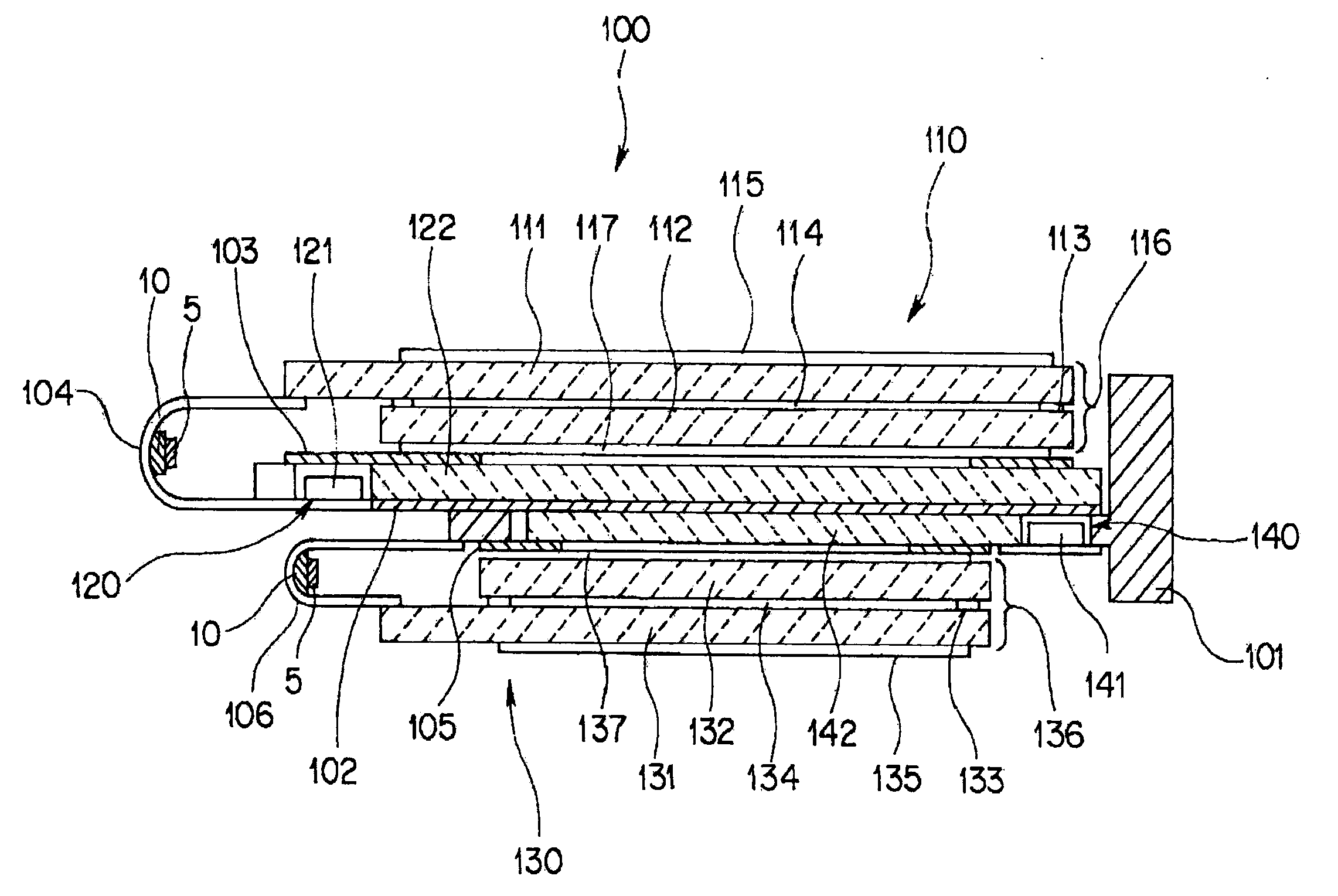
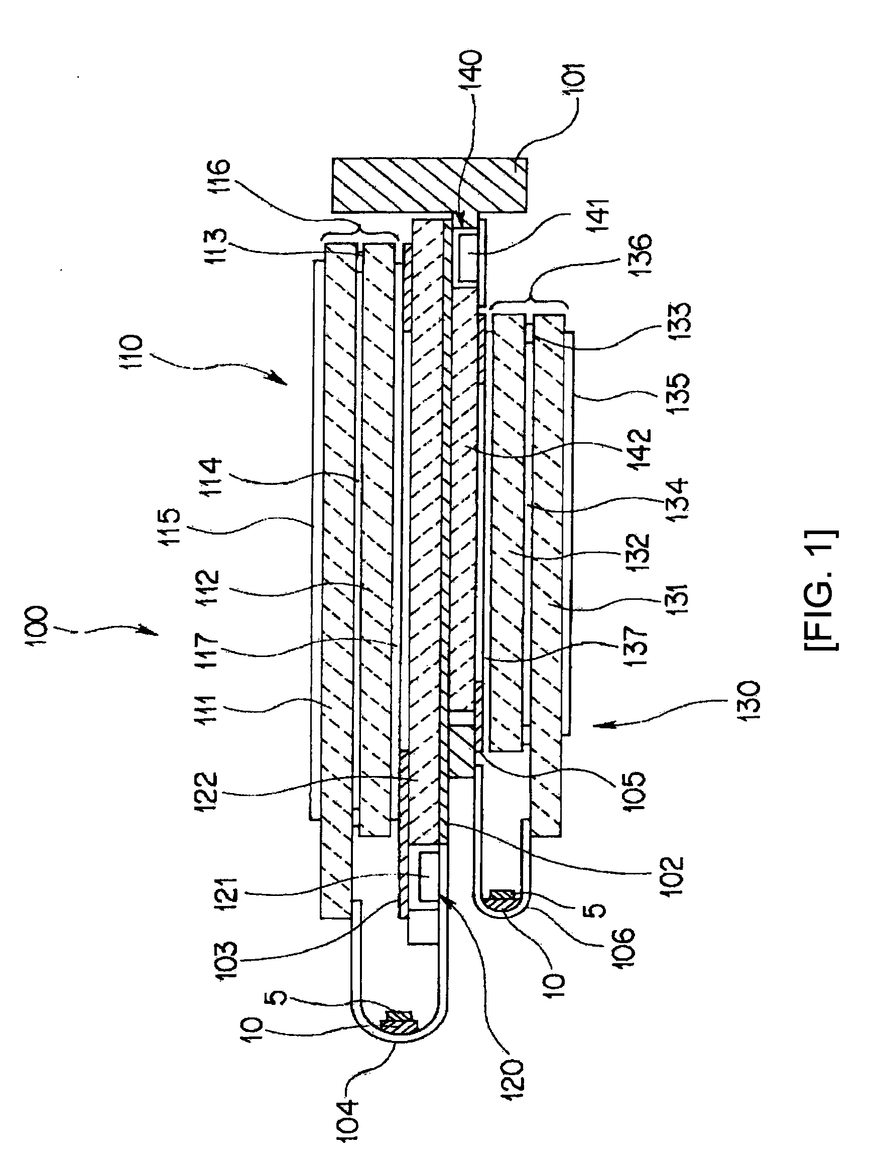
[0065]FIG. 1 is a cross-sectional view showing a liquid crystal display device according to an embodiment of the present invention. In the description, a surface on the upper side of the drawing is designated as a front surface, and a surface on the lower side of the drawing is designated as a back surface for convenience of explanation.

[0066]As shown in FIG. 1, a liquid crystal display device 100 as an electro-optical apparatus is a so-called back surface integrated liquid crystal display device including a first liquid crystal display module 110 and a second liquid crystal display module 130 as principal components.

[0067]The first liquid crystal display module 110 includes a first liquid crystal display panel 116 as an electro-optical panel having a display section, an FPC (flexible printed circuit) board 104 electrically connected to the first liquid crystal display panel 116, a circuit board 10 on which an electronic component 5 is mounted, and a backlight unit 120 as a light so...


PUM

PropertyMeasurementUnit
thicknessaaaaaaaaaa
thicknessaaaaaaaaaa
flexibleaaaaaaaaaa

Abstract

An electro-optical apparatus comprising an electro-optical panel including a display section, a flexible printed circuit board, and a rigid circuit board. The flexible printed circuit board includes a first terminal connected to the electro-optical panel and a second terminal connected to an external circuit. The rigid circuit board includes a first surface on which electronic components are mounted and a second surface mounted to the flexible printed circuit board. The second surface of the rigid circuit board is opposite to the first surface. An entirety of the rigid circuit board is stacked on the flexible printed circuit board within the flexible printed circuit board. The rigid circuit board is electrically connected to the flexible printed circuit board. The flexible printed circuit board is bent toward the external circuit.

Description

CROSS-REFERENCE TO RELATED APPLICATIONS[0001]This application is a continuation of U.S. patent application Ser. No. 10 / 944,674 filed on Sep. 17, 2004, which claims priority to Japanese Patent Application Nos. 2003-327992 filed Sep. 19, 2003 and 2004-182455 filed Jun. 21, 2004. The entire disclosures of each of the above applications are incorporated herein by reference.BACKGROUND[0002]1. Technical Field[0003]The present invention relates to an electro-optical apparatus, a flexible printed circuit board, a manufacturing method for an electro-optical apparatus, and electronic equipment.[0004]2. Background Art[0005]A principal portion of an electro-optical apparatus used as a display of electronic devices such as a mobile phone includes an electro-optical panel having an image display section using liquid crystal or the like as electro-optical material and being constituted of a plurality of picture elements, a drive circuit unit including electronic components required for driving the...

Claims


Application Information

Patent Timeline
Patent Type & Authority Applications(United States)
IPC IPC(8): H05K1/00G02F1/1333G02F1/13G02F1/13357G02F1/1345G09F9/00H05K1/14H05K3/36
CPCG02F1/133615G02F1/13452H05K1/141H05K2201/055H05K3/361H05K2201/045H05K1/147G02F1/1345
Inventor YUMOTO, MASANORIHIRANO, YOSHIHISAIMAEDA, CHIAKI
Owner BOE TECH GRP CO LTD
Why Eureka
Try Eureka