
Timepiece With Internal Antenna

a timepiece and antenna technology, applied in the field of timepieces with internal antennas, can solve the problems of easy interference of patch antenna signal reception, low reception performance, and complicated further reduction in size, and achieve the effect of good reception performan

Active Publication Date: 2011-03-03
SEIKO EPSON CORP
View PDF14 Cites 103 Cited by
  • Summary
  • Abstract
  • Description
  • Claims
  • Application Information

AI Technical Summary

Benefits of technology

A timepiece with an internal antenna according to the present invention can ensure good reception performance even when the outside case is metal.
A patch antenna is a flat, unidirectional antenna with narrow directivity, but because the circuit board on which the patch antenna is mounted also functions as a ground plate, radio waves incident from an external source can be reflected by the circuit board and guided to the antenna. As a result, the antenna can receive not only radio waves that are directly incident to the antenna, but also signals that are reflected by the circuit board and indirectly incident. The reception performance of the antenna can therefore be further improved.

Problems solved by technology

Recent technological advances in dielectric materials and radio sensitivity have enabled reducing the size of the patch antenna to some degree, but further reduction in size is complicated by the need to ensure the required reception performance.
However, signal reception by the patch antenna will be easily affected if a case made from metal or other conductive material is adjacent to the side of the antenna (the outside circumference side facing the inside circumference surface of the case), and reception performance will drop.
However, a problem with the timepiece taught in JP-T-2007-526985 is that the plastic bezel occupies a large area and the quality of the timepiece therefore appears lower.
A significant drop in the reception performance of the antenna is therefore a problem.

Method used


Image

  • Timepiece With Internal Antenna
  • Timepiece With Internal Antenna
  • Timepiece With Internal Antenna

Examples


embodiment 1

A first embodiment of the invention is described below with reference to the accompanying figures.

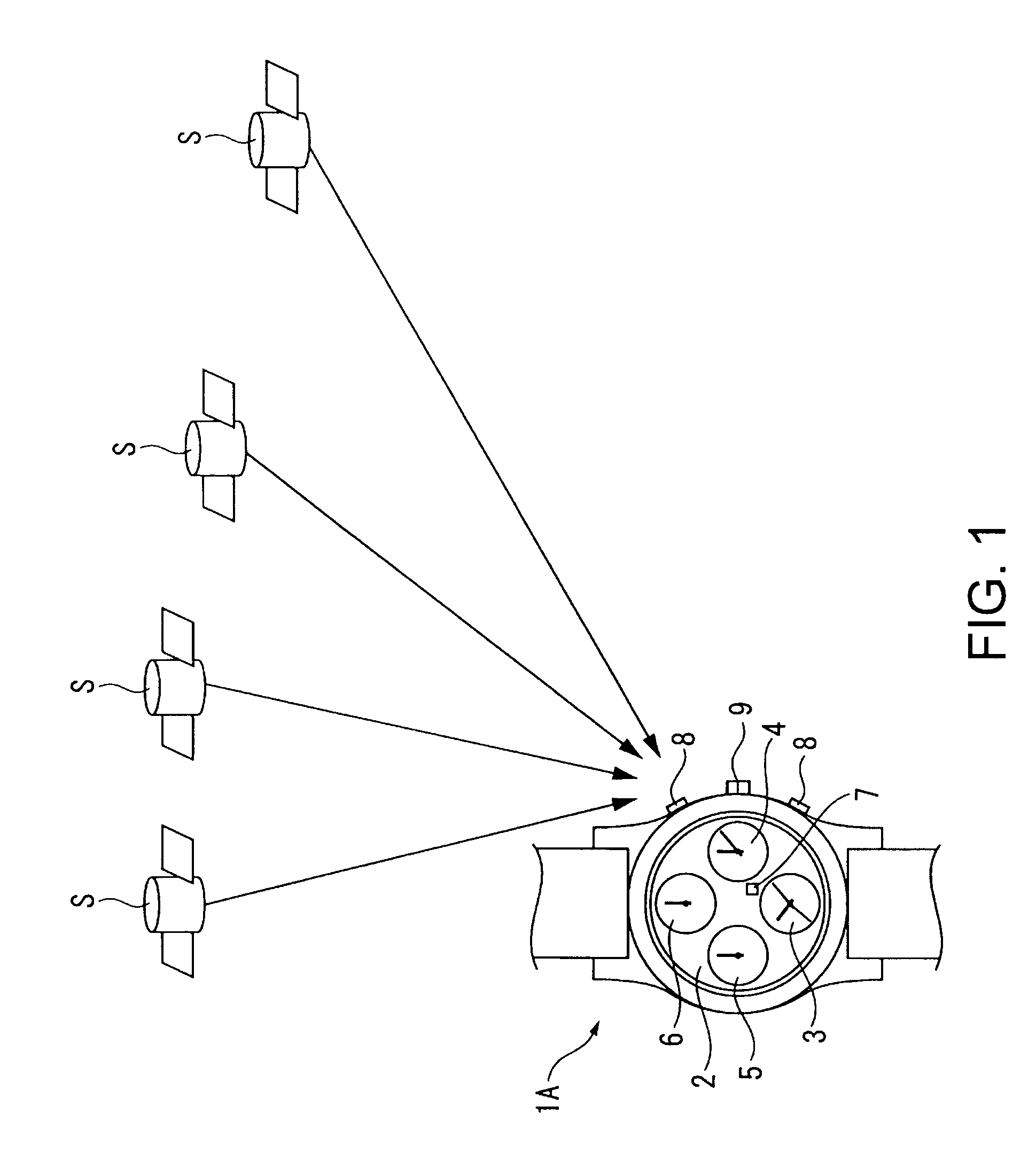
FIG. 1 shows a GPS wristwatch 1A according to a preferred embodiment of a timepiece with an internal antenna according to the invention.

As shown in FIG. 1, the GPS wristwatch 1A is configured to adjust the internally kept time by receiving satellite signals and acquiring satellite time information from a plurality of GPS satellites S orbiting the Earth in space on specific orbits.

Note that the GPS satellites S are an example of a positioning information satellite in the invention, and a plurality of satellites orbit the Earth in space. Today there are approximately 30 GPS satellites S in orbit.

Operating buttons 8 for external operations and a crown 9 are also disposed to the GPS wristwatch 1A.

Configuration of a GPS Wristwatch

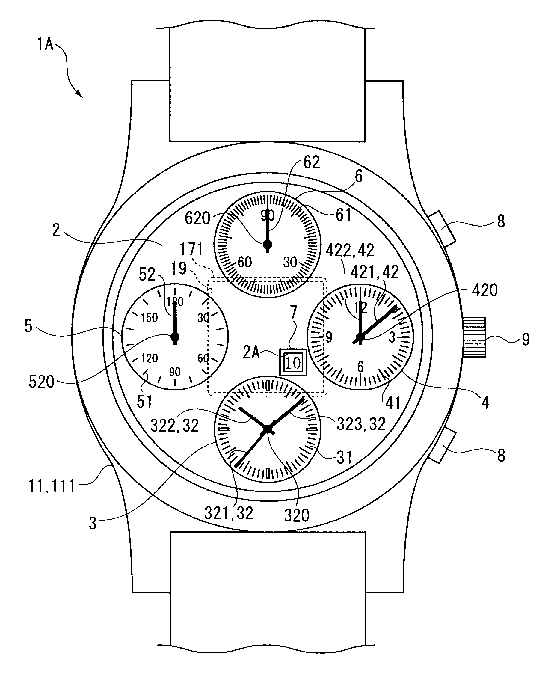
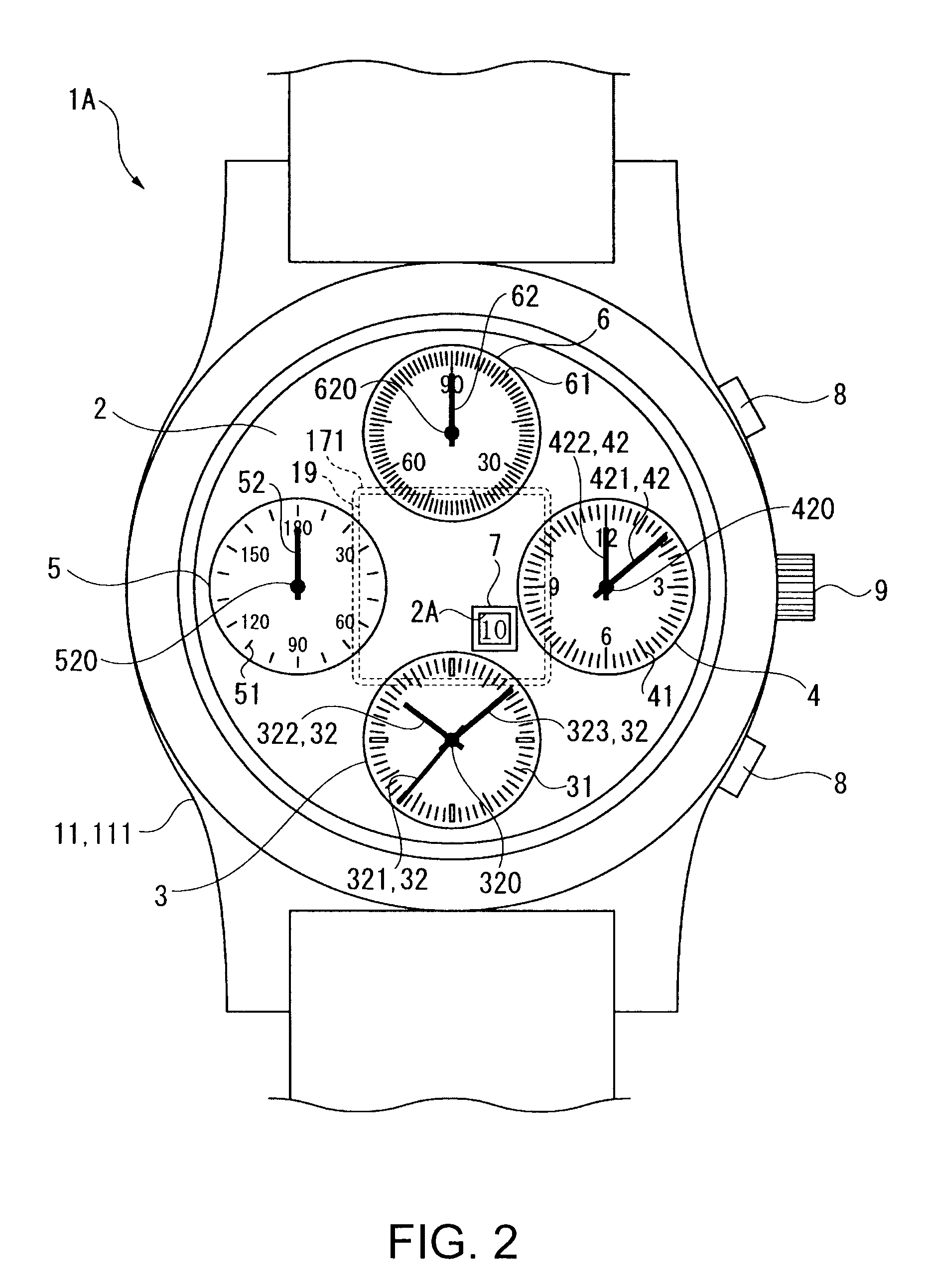
FIG. 2 is a is a plan view of the GPS wristwatch 1A. FIG. 3 is a section view of the GPS wristwatch 1A. FIG. 4 is a plan view of the movement 10.

The GPS wristwatch ...

embodiment 2

FIG. 7 is a section view of a GPS wristwatch 1B according to a second embodiment of the invention. FIG. 8 is an exploded oblique view schematically showing the main parts of the GPS wristwatch 1B according to this embodiment of the invention. Note that like parts in this embodiment and the foregoing embodiment are identified by like reference numerals and further description thereof is omitted.

Power is supplied to the storage cell 14 by the charge coil 82 in the foregoing embodiment, and this embodiment differs by using a solar panel 87 to supply power to the storage cell 14.

In addition, because this embodiment does not use a charge coil 82, there is no need to use a glass second back cover part 112B for power transmission, and the entire back cover 112 is metal.

As shown in FIG. 7 and FIG. 8, the solar panel 87 is disposed between the dial 2 and the date wheel 18. This solar panel 87 is annular with a rectangular window 87A that exposes the patch antenna 19 in the middle. The window...

embodiment 3

FIG. 9 is an exploded oblique view showing the main parts of a GPS wristwatch 1C according to a third embodiment of the invention. Note that like parts in this embodiment and the first embodiment are identified by like reference numerals and further description thereof is omitted.

The patch antenna 19A in this embodiment of the invention is round in plan view, and thus differs in shape from the rectangular patch antenna 19 described in the first embodiment.

Note, further, that this embodiment has a solar panel 87 but can be configured without a solar panel 87.

Because the patch antenna 19A is round in plan view, the window 87A in the solar panel 87 and the opening 171 in the base plate 17 are also round conforming to the shape of the patch antenna 19A. The antenna substrate 191A is also round in plan view.

In addition to the effects of the first and second embodiments described above, the GPS wristwatch 1C according to this embodiment of the invention has the following effect.

Because th...


PUM


Abstract

A timepiece with an internal antenna, including: a case that is made from a conductive material; a movement that is housed in the case and has a plurality of motors that drive staffs disposed at a plurality of locations; a dial that is made from a nonconductive material; and a patch antenna that is disposed inside the case on the back side of the dial, receives radio signals transmitted from an external source, and includes a dielectric and an electrode formed in the dielectric; wherein the patch antenna is disposed separated at least a specific distance from the inside surface of the case, and the staffs are disposed between the case and the patch antenna.

Description

CROSS-REFERENCE TO RELATED APPLICATION(S)Japanese Patent Application Nos. 2009-201557, filed Sep. 1, 2009, and 2010-143886, filed Jun. 24, 2010, are hereby incorporated by reference in their entirety.BACKGROUND1. Field of InventionThe present invention relates to a timepiece with an internal antenna, and more particularly to a timepiece with a built-in patch antenna (microstrip antenna) that receives radio frequency signals transmitted from an external source.2. Description of Related ArtTimepieces that have an antenna for receiving radio frequency signals are known from the literature. Included in these RF signals are satellite signals transmitted from positioning information satellites, for example.A wristwatch that has a patch antenna for receiving satellite signals as taught in JP-T-2007-526985 (Japanese translation of PCT international application JP-A-2007-526985) is an example of a timepiece with an internal antenna.More specifically, JP-T-2007-526985 describes a wristwatch c...

Claims


Application Information

Patent Timeline
IPC IPC(8): G04C11/02G04C3/00G04G21/04G04C10/02G04R60/12
CPCG04G5/002G04G9/0076G04G21/04H01Q1/273H01Q1/52G04R60/10G04R60/12G04R20/04G04C9/02G04C10/02H01Q9/0407G04C10/00G04C9/08G04R20/02G04R60/06G04G17/08
Inventor FUJISAWA, TERUHIKO
Owner SEIKO EPSON CORP
Learn More