Detachable aromatic nebulizing diffuser

a diffuser and aromatic technology, applied in the field of nebulizing diffusers, can solve the problems of not being able to simulate the natural visual effect of flying mist, conventional essential oil nebulizing diffusers with light emitting means cannot exhibit a lighting effect apparently at daylight, and conventional essential oil nebulizing diffusers cannot create colorful mist scenery, etc., to achieve the effect of convenient cleaning and convenient detachability

Inactive Publication Date: 2011-03-03
HSIAO MING JEN
View PDF6 Cites 21 Cited by
  • Summary
  • Abstract
  • Description
  • Claims
  • Application Information

AI Technical Summary

Benefits of technology

[0011]The present invention has been accomplished under the circumstances in view. It is main object of the present invention to provide an aromatic nebulizing diffuser, which is easily detachable, facilitating cleaning work.

Problems solved by technology

They cannot simulate the natural visual effect of a flying mist caused by the impact of a waterfall.
Further, conventional essential oil nebulizing diffusers with light emitting means cannot exhibit a lighting effect apparently at daylight.
Due to the use of a light-tight housing, conventional essential oil nebulizing diffusers cannot create a colorful mist scenery at night.
Further, conventional aromatic nebulizing diffusers commonly use screws to affix component parts together, complicating mounting and dismounting procedures.
It takes much time and labor to practice a cleaning work.
This gradually reducing diameter design tends to cause the generated fine mist to be condensed into water drops, lowering the fin mist generating performance.
Further, conventional aromatic nebulizing diffusers may use an electric fan to cause currents of air for flashing an essential oil into a mist.
However, due to limited air path, the pressure of the induced currents of air is not sufficient for causing a fine mist in a big area, lower the nebulizing diffusing performance.
If an aromatic nebulizing diffuser is placed in a corner area of a house, the generated fine mist will not be evenly distributed in the house.

Method used


Image

  • Detachable aromatic nebulizing diffuser
  • Detachable aromatic nebulizing diffuser
  • Detachable aromatic nebulizing diffuser

Examples


Embodiment Construction

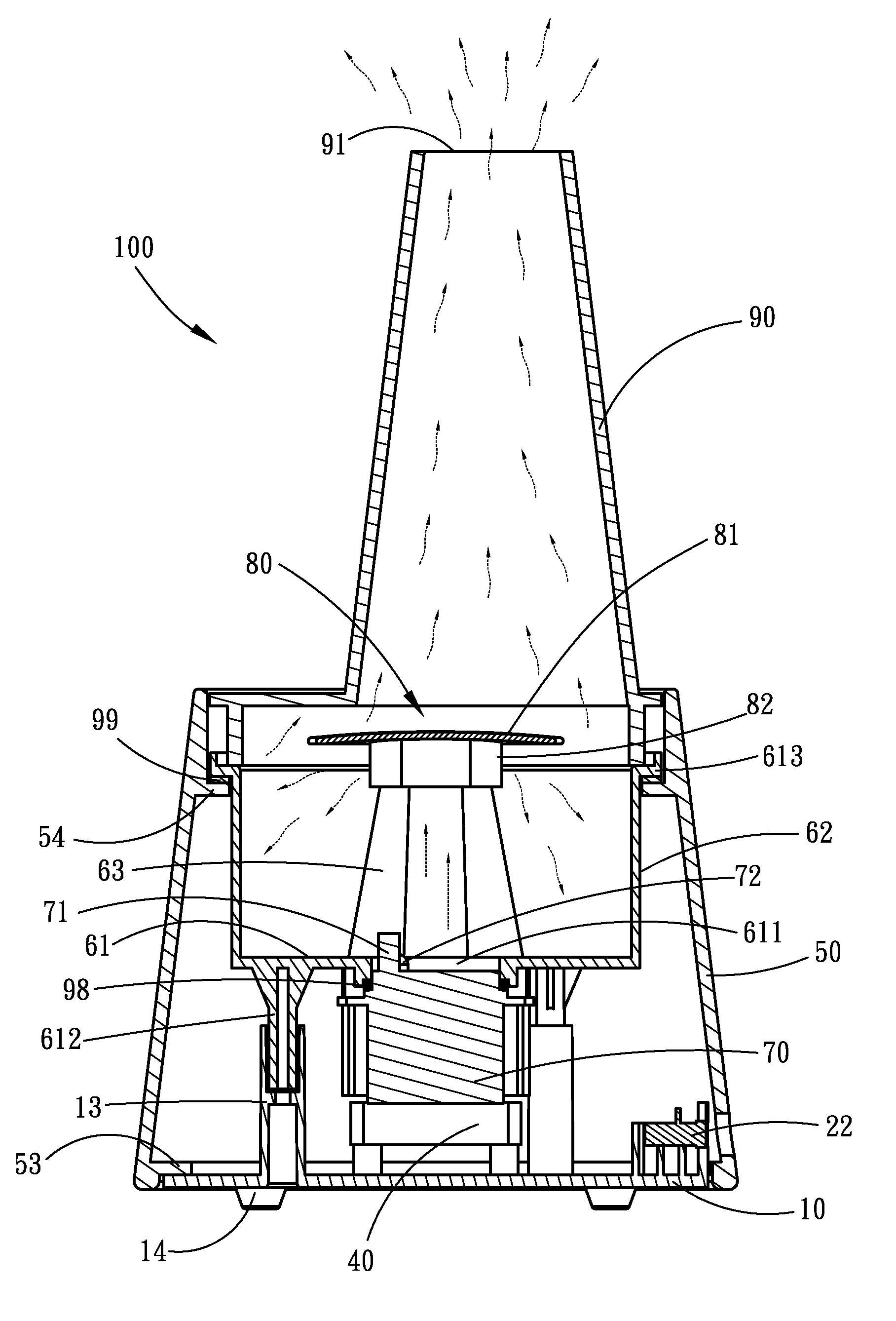
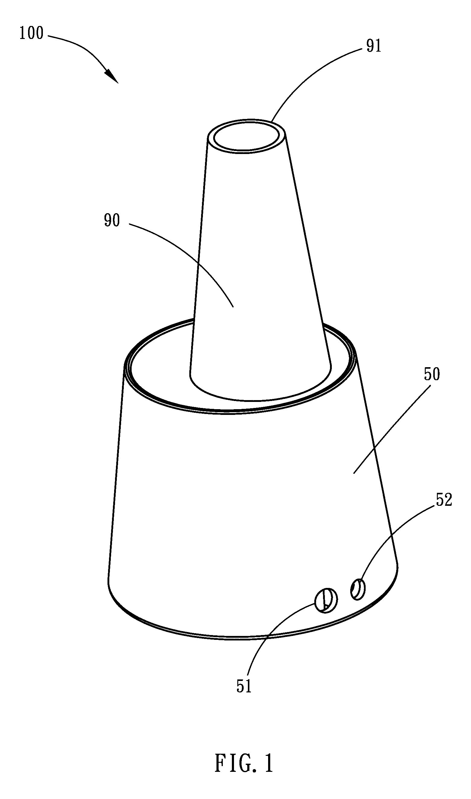
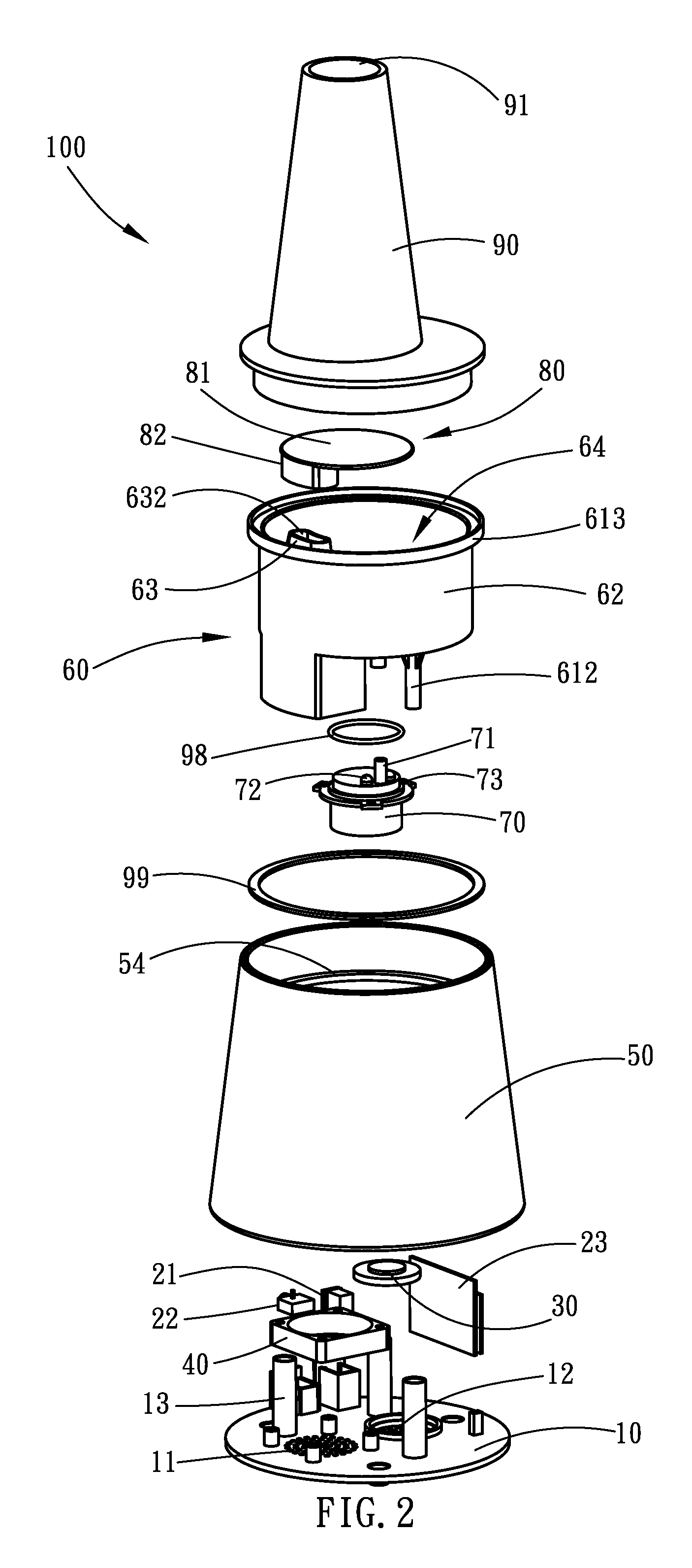
[0028]Referring to FIGS. 1 and 5, a detachable aromatic nebulizing diffuser 100 in accordance with a first embodiment of the present invention is shown comprising a base panel 10, a power jack 21, an electric fan 40, a lower housing 50, a fluid container 60, a ultrasonic oscillator 70, a water baffle 80 and a top cover 90.

[0029]Referring to FIGS. 2˜4, the base panel 10 has a plurality of air vents 11 cut through the top and bottom walls thereof and a plurality of tubular upright posts 13 perpendicularly extended from the top wall.

[0030]Referring to FIG. 2, the power jack 21 is mounted on the base panel 10 for the connection of an external power cable for power input.

[0031]Referring to FIG. 2, the electric fan 40 is mounted on the base panel 10 corresponding to the air vents 11 and electrically connected to the power jack 21 to obtain the necessary working voltage from the power jack 21 for drawing outside fresh air into the inside of the detachable nebulizing diffuser 100.

[0032]Refe...


PUM

PropertyMeasurementUnit
diameteraaaaaaaaaa
oscillation energyaaaaaaaaaa
voltageaaaaaaaaaa

Abstract

A detachable aromatic nebulizing diffuser includes a base panel, an electric fan, a fluid container, an ultrasonic oscillator, a power jack, a water baffle, a lower housing and a top cover. The ultrasonic oscillator oscillates ultrasonic waves to cause an aromatic fluid in the fluid container into a fine mist that is carried by currents of air caused by the electric fan and guided through an air duct in the fluid container. The fluid container has bottom mounting rods detachably plugged into respective tubular upright posts of the base panel, facilitating mounting and dismounting. The water baffle and the top cover are light transmissive for creating a visual effects upon working of a light source that is carried on the ultrasonic oscillator.

Description

BACKGROUND OF THE INVENTION[0001]1. Field of the Invention[0002]The present invention relates to a nebulizing diffuser and more particularly, to a detachable aromatic nebulizing diffuser that diffuses essential oils or any of a variety of aromatic fluids on a refreshing current of air rapidly and efficiently.[0003]2. Description of the Related Art[0004]Regular aromatic nebulizing diffusers or essential oil diffusers commonly use an ultrasonic oscillator to generate a high ultrasonic energy for causing atomization of an essential oil for application. Separation of electric charges in falling rain, caused by breaking up of the water droplets, the drops becoming positively charged and the air negatively charged. This separation of electric charges accompanying the aerodynamic breakup of water drops is known as spray electrification, the waterfall effect or Lenard effect. Conventional aromatic nebulizing diffusers simply produce an upwardly flying mist of aromatic vapor. They cannot sim...

Claims


Application Information

Patent Timeline
Patent Type & Authority Applications(United States)
IPC IPC(8): H04R1/02B01F3/04
CPCH04R1/028A61L9/122
Inventor JORGENSEN, CARSTEN
Owner HSIAO MING JEN
Why Eureka
Try Eureka