Method and system for banding compensation using electrostatic voltmeter based sensing

a technology of electrostatic voltmeter and banding compensation, applied in the field of banding compensation using electrostatic voltmeter based sensing, can solve problems such as problems, reducing the signal-to-noise ratio (snr), and manifesting periodic non-uniformities in output prints

Active Publication Date: 2011-03-03
XEROX CORP
View PDF38 Cites 14 Cited by
  • Summary
  • Abstract
  • Description
  • Claims
  • Application Information

AI Technical Summary

Benefits of technology

According to one aspect of the present disclosure, a method for compensating for an image quality defect in an image printing system comprising at least one marking engine, the at least one marking station comprising a charging device for charging the image bearing surface, an exposing device for irradiating and discharging the image bearing surface to form a latent image, a developer unit for developing toner to the image bearing surface, and a transfer unit for transferring toner from the image bearing surface to an image accumulation surface is provided. The method includes sensing the image quality defect on an image bearing surface by an electrostatic voltmeter (ESV) in the image printing system; determining the frequency, amplitude, and / or phase of the image quality defect by a processor; and compensating for the image quality defect by modulating the power of the exposing device during an expose process.
According to another aspect of the present disclosure, a method for compensating for an image quality defect in an image printing system comprising at least one marking station comprising a charging device for charging the image bearing surface, an exposing device for irradiating and discharging the image bearing surface to form a latent image, a developer unit for developing toner to the image bearing surface, and a transfer unit for transferring toner from the image bearing surface to an image accumulation surface is provided. The method includes sensing the image quality defect on an image bearing surface by an electrostatic voltmeter (ESV) in the image printing system; determining the frequency, amplitude, and / or phase of the image quality defect by a processor; and compensating for the image quality defect by modifying image content.
According to another aspect of the present disclosure, a system for compensating for an image quality defect in an image printing system is provided. The system includes a marking engine; an electrostatic voltmeter (ESV) configured to sense the image quality defect on an image bearing surface; a processor, wherein the processor is configured to determine the frequency, amplitude, and / or phase of the banding defect based on readings of the ESV; and a controller, wherein the controller is configured to compensate for the image quality defect by modulating power of the exposing device during an expose process.
According to another aspect of the present disclosure, a system for compensating for an image quality defect in an image printing system is provided. The system includes a marking engine; an electrostatic voltmeter (ESV) configured to sense the image quality defect on an image bearing surface; a processor, wherein the processor is configured to determine the frequency, amplitude, and / or phase of the banding defect based on readings of the ESV; and a controller, wherein the controller is configured to compensate for the image quality defect by modifying image content.

Problems solved by technology

Banding in a xerographic engine may be caused by charge non-uniformity on the image bearing surface, variations in a Photo Induced Discharge Curve (PIDC), image bearing surface motion quality variations, and / or image bearing surface “out-of-round” that lead to periodic non-uniformities manifesting in the output print.
Image bearing surface motion quality variations may be caused by vibration, motion backlash, gear train interactions, mechanical imbalances, friction, among other factors.
These problems can exist at build, or through degradation with component age.
The problem with an ADC reading is that sources of noise due to development, first transfer, and retransfer on downstream image bearing surfaces are introduced, therefore decreasing the signal-to-noise ratio (SNR).

Method used


Image

  • Method and system for banding compensation using electrostatic voltmeter based sensing
  • Method and system for banding compensation using electrostatic voltmeter based sensing
  • Method and system for banding compensation using electrostatic voltmeter based sensing

Examples


Embodiment Construction

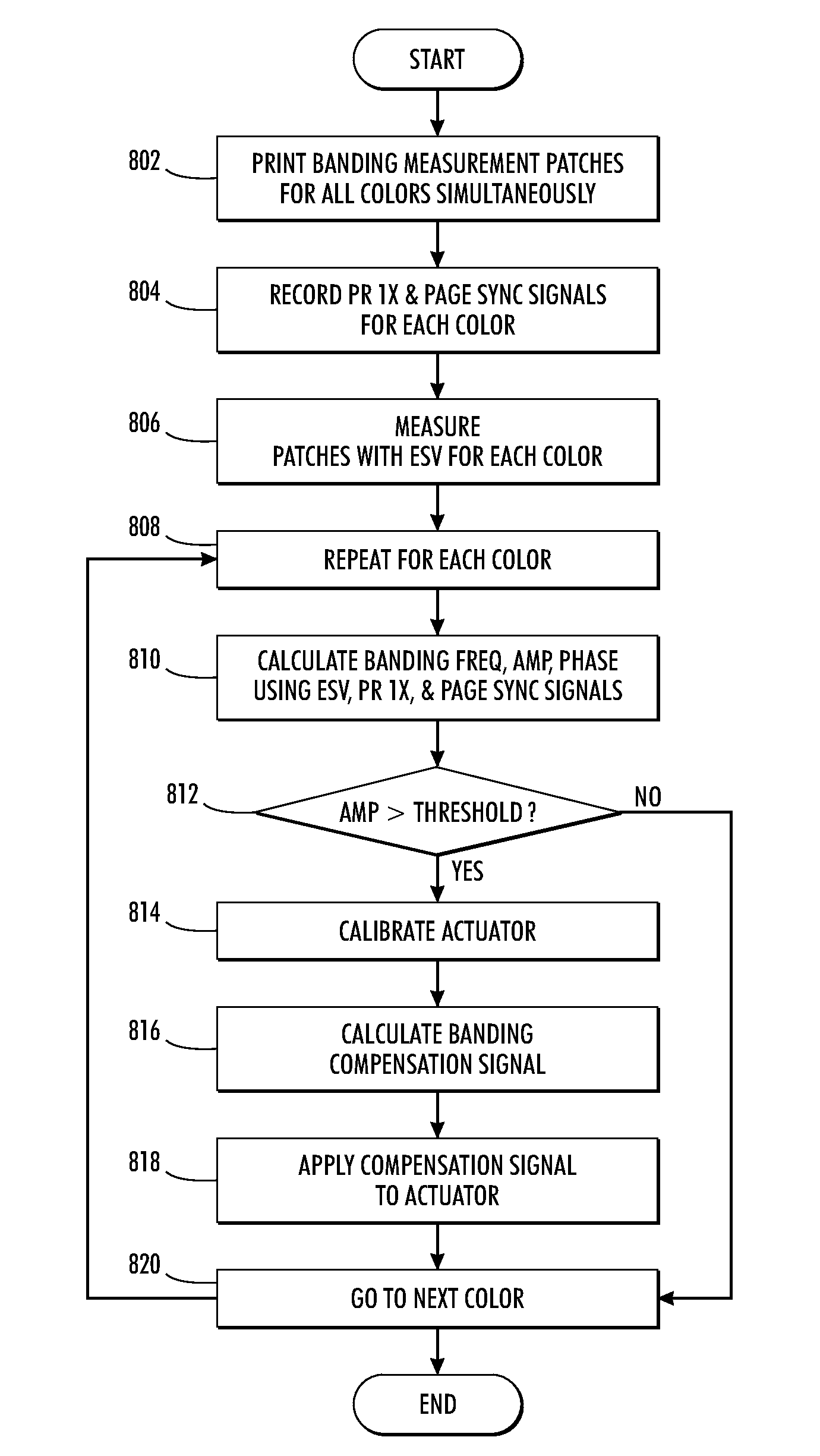
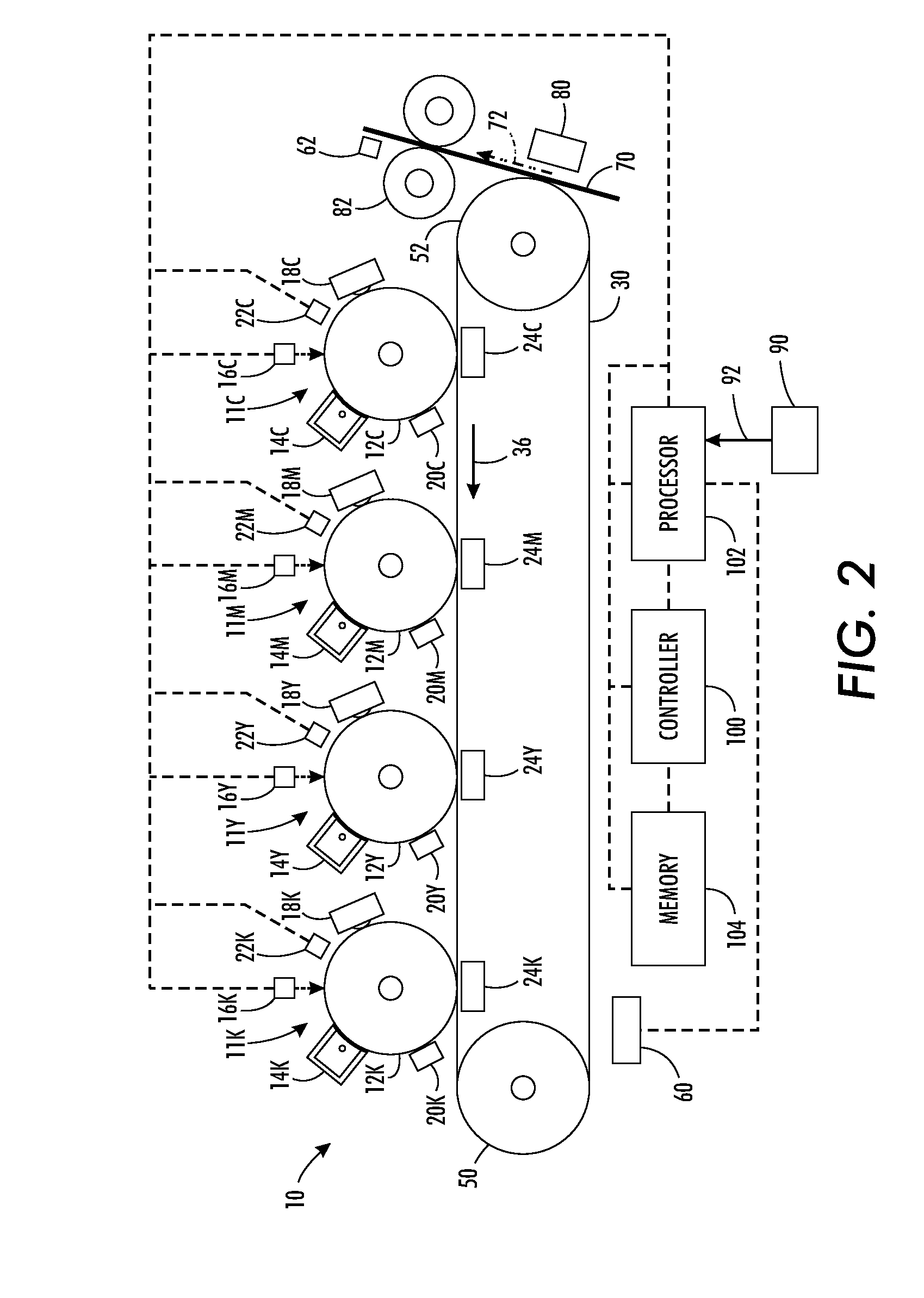
The present disclosure addresses an issue in the area of banding correction. The present disclosure proposes a use of Electrostatic Voltmeter (ESV) sensors to measure charge density variation, or voltage non-uniformity, on the image bearing surface to sense periodic image quality defects. Image quality defects, such as banding defects, may be caused by charge non-uniformity, variations in the Photo Induced Discharge Curve (PIDC), image bearing surface motion quality variations, and / or image bearing surface “out-of-round.” The present disclosure proposes compensating for the image quality defects by generating a compensation signal. In one embodiment, the compensation signal may modulate power of an exposing device, such as a Raster Output Scanner (ROS), during the expose process. In another embodiment, the compensation signal may modify image content. Such an embodiment may have a marking engine with an image bearing surface that is synchronous with the printed pages such that each ...


PUM


Abstract

A method and system for compensating for an image quality defect in an image printing system comprising at least one marking station, the at least one marking station comprising a charging device for charging the image bearing surface, an exposing device for irradiating and discharging the image bearing surface to form a latent image, a developer unit for developing toner to the image bearing surface, and a transfer unit for transferring toner from the image bearing surface to an image accumulation surface is provided. The method includes sensing the image quality defect on an image bearing surface by an electrostatic voltmeter (ESV) in the image printing system and determining the frequency, amplitude, and/or phase of the image quality defect by a processor. In one embodiment, the method includes compensating for the image quality defect by modulating the power of an exposing device during an expose process. In another embodiment, the method includes compensating for the image quality defect by modifying image content.

Description

FIELDThe present disclosure relates to a method and system for compensating for image quality defects using an Electrostatic Voltmeter (ESV).BACKGROUNDAn electrophotographic, or xerographic, image printing system employs an image bearing surface, such as a photoreceptor drum or belt, which is charged to a substantially uniform potential so as to sensitize the surface thereof. The charged portion of the image bearing surface is exposed to a light image of an original document being reproduced. Exposure of the charged image bearing surface selectively dissipates the charge thereon in the irradiated areas to record an electrostatic latent image on the image bearing surface corresponding to the image contained within the original document. The location of the electrical charge forming the latent image is usually optically controlled. More specifically, in a digital xerographic system, the formation of the latent image is controlled by a raster output scanning device, usually a laser or ...

Claims


Application Information

Patent Timeline
Patent Type & Authority Applications(United States)
IPC IPC(8): G03G15/00G03G15/043
CPCG03G15/5037G03G15/043
Inventor KOZITSKY, VLADIMIRPAUL, PETER
Owner XEROX CORP
Why Eureka
Try Eureka