
Development apparatus

a technology of development apparatus and developer, applied in the direction of electrographic process apparatus, instruments, optics, etc., can solve the problems of unstable quantity of developer passing through the gap, unstable and difficulty in completely eliminating the occurrence of developer non-flowing layer, etc., to achieve the effect of stabilizing the thickness of developer conveyed

Active Publication Date: 2011-03-03
CANON KK
View PDF17 Cites 12 Cited by
  • Summary
  • Abstract
  • Description
  • Claims
  • Application Information

AI Technical Summary

Benefits of technology

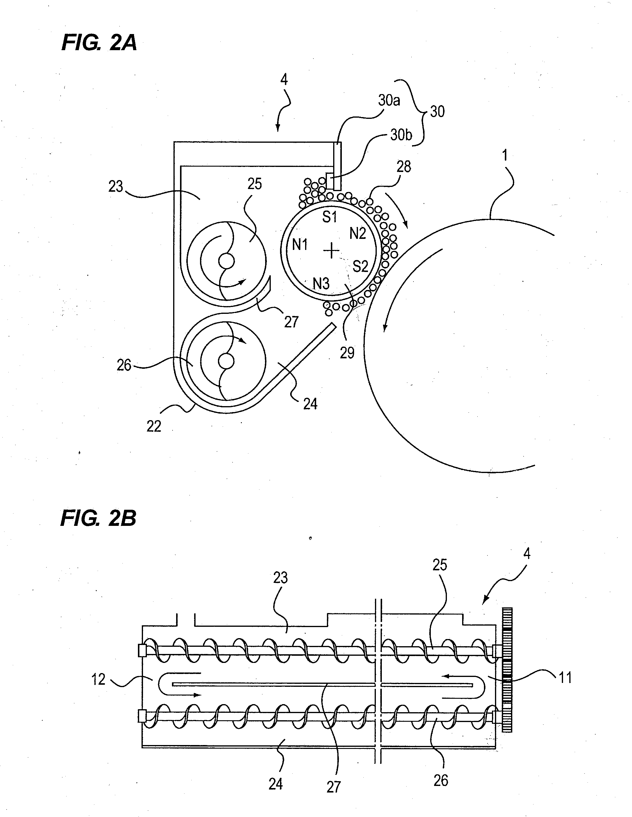
[0016]The present invention has been made in views of the above problems and the present invention provides a development apparatus capable of stably maintaining thickness of developer conveyed to a developing area for the long term while eliminating a tone layer from the next upstream part of a restriction blade before the toner layer grows.

Problems solved by technology

With the development apparatus performing the thickness restriction of developer borne at the developing sleeve surface by the restriction blade, there may be a case that following problems occur.
Consequently, the developer quantity conveyed to the developing area fluctuates and a problem such as darkness fluctuation occurs.
However, when quantity of the developer supplied to the restriction blade is decreased, there is apt to arise a new problem that quantity of the developer passing through the gap becomes unstable.
Accordingly, it is difficult to completely eliminate occurrence of the developer non-flowing layer.
However, bearings to support the toner conveying member and drive unit are required, so that structure complication and cost increase are unavoidable.
Further, since the toner conveying member is driven in the opposite direction at a position opposed to the developer bearing member, there may be a risk that developer rapidly deteriorates since strong stress is to be applied to the developer.
In addition, in the case of high-speed rotation, there may be a risk that developer is melted and fixed due to generation of heat.
However, in Japanese Patent Laid-Open No. 2005-092061, there may be a risk that a toner layer is formed against the developer flowing layer during lasting long usage and starts to disturb developer flowing when the developer non-flowing layer is formed even in the slight area.

Method used


Image

  • Development apparatus
  • Development apparatus
  • Development apparatus

Examples


first embodiment

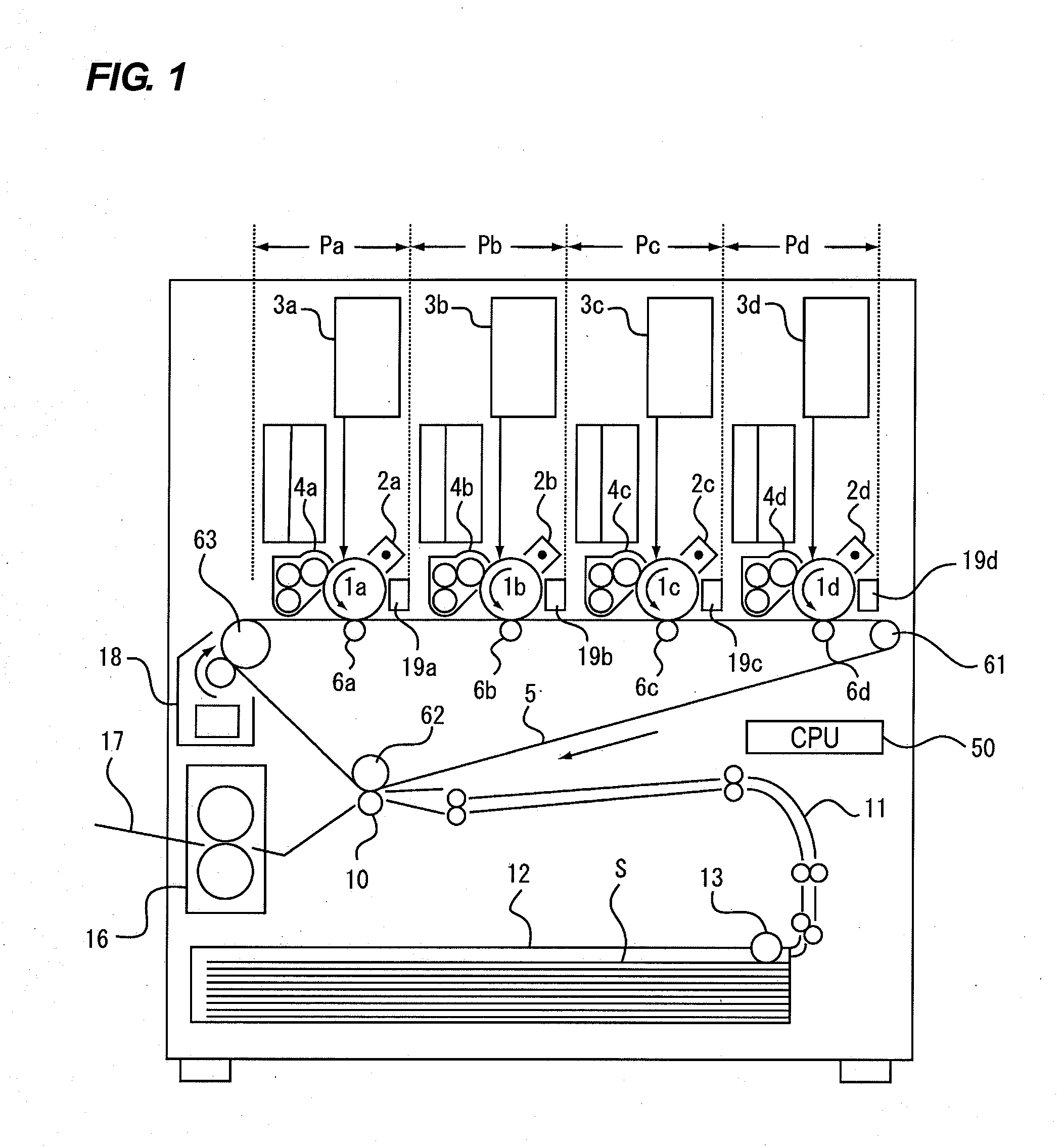
[0032]A general configuration of an image forming apparatus including a development apparatus will be described with reference to FIG. 1. FIG. 1 is a schematic sectional view illustrating the general configuration of a full-color image forming apparatus which adopts an electrophotographic system being an embodiment of an image forming apparatus.

[0033]As illustrated in FIG. 1, the image forming apparatus includes four image forming portions P (Pa, Pb, Pc, Pd) as image forming units. Each of the image forming portions Pa to Pd includes a drum-shaped electrophotographic photosensitive member, that is, a photosensitive drum 1 (1a, 1b, 1c, 1d), being rotated in the direction of the arrow (i.e., the counterclockwise direction) as an image bearing member. A charger 2 (2a, 2b, 2c, 2d), a development apparatus 4 (4a, 4b, 4c, 4d) and a cleaning device 19 (19a, 19b, 19c, 19d) are arranged around each photosensitive drum respectively as process unit. In addition, a laser beam scanner 3 (3a, 3b,...

second embodiment

[0110]The second embodiment is different from the abovementioned first embodiment by the following described points. The rest of the points is configured to be similar to the first embodiment. Accordingly, in the description of the second embodiment, the same numeral is given to the same structural element corresponding to the structural element of the first embodiment and the detailed description will not be repeated.

[0111]In the first embodiment, the boundary surface between the flowing layer and the non-flowing layer determined by the shearing strength s and the shearing stress t is moved by lessening the shearing strength s. Here, when the shearing stress t is changed in addition to changing the shearing strength s, the movement of the boundary surface can be performed more effectively. In order to move the boundary surface between the flowing layer and the non-flowing layer in the direction being apart from the circumferential surface of the developing sleeve 28, the shearing s...


PUM


Abstract

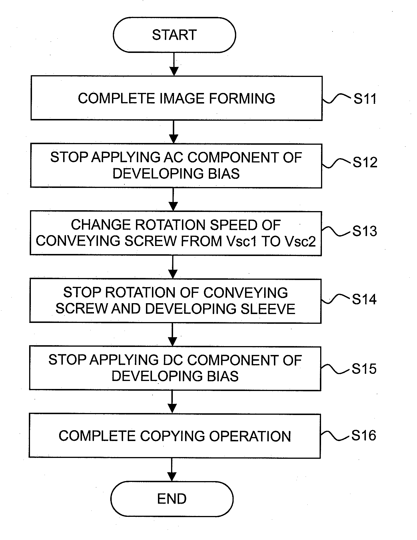
In a development apparatus including conveying screws which circulates and conveys developer in a developer container as being rotated, a developing sleeve which bears and conveys developer in the developer container as being rotated, and a restriction blade which restricts developer quantity at the developing sleeve, the developer container includes a supply chamber to supply developer to the developing sleeve and a retrieval chamber to retrieve developer from the developing sleeve, and rotation speed of the conveying screws or rotation speed of the developing sleeve is changed so that Vsc / Vsl during image forming is not performed is to be smaller than that during image forming is performed, as Vsc denotes the rotation speed of the conveying screws and Vsl denotes the rotation speed of the developing sleeve.

Description

BACKGROUND OF THE INVENTION[0001]1. Field of the Invention[0002]The present invention relates to a development apparatus in an image forming apparatus which visualizes an electrostatic latent image formed on an image bearing member with developer including toner in an electrophotographic system or an electrostatic recording system, in particular, related to a development apparatus mounted on an image forming apparatus.[0003]2. Description of the Related Art[0004]Conventionally, in an image forming apparatus utilizing an electrophotographic system, an electrostatic latent image formed on a photosensitive member as an image bearing member is visualized as a toner image with toner in developer by utilizing a development apparatus.[0005]The most popular development apparatus is constituted with a developer container to accommodate developer, a conveying member to convey developer in the developer container while agitating and mixing, a developer bearing member to bear and convey develop...

Claims


Application Information

Patent Timeline
Patent Type & Authority Applications(United States)
IPC IPC(8): G03G15/08
CPCG03G15/0806G03G2215/0827G03G15/0935G03G15/065G03G15/08G03G15/0812G03G15/0877G03G15/0891
Inventor SAKAMAKI, TOMOYUKI
Owner CANON KK
Learn More