
Expandable Electrode Pad

Active Publication Date: 2011-03-03
CROSBY WILLIAM
View PDF22 Cites 181 Cited by
  • Summary
  • Abstract
  • Description
  • Claims
  • Application Information

AI Technical Summary

Benefits of technology

[0019]The present invention comprises a device and method of use that has one or more of the following features and/or steps, which alone or in any combination may comprise patentable subject matter.
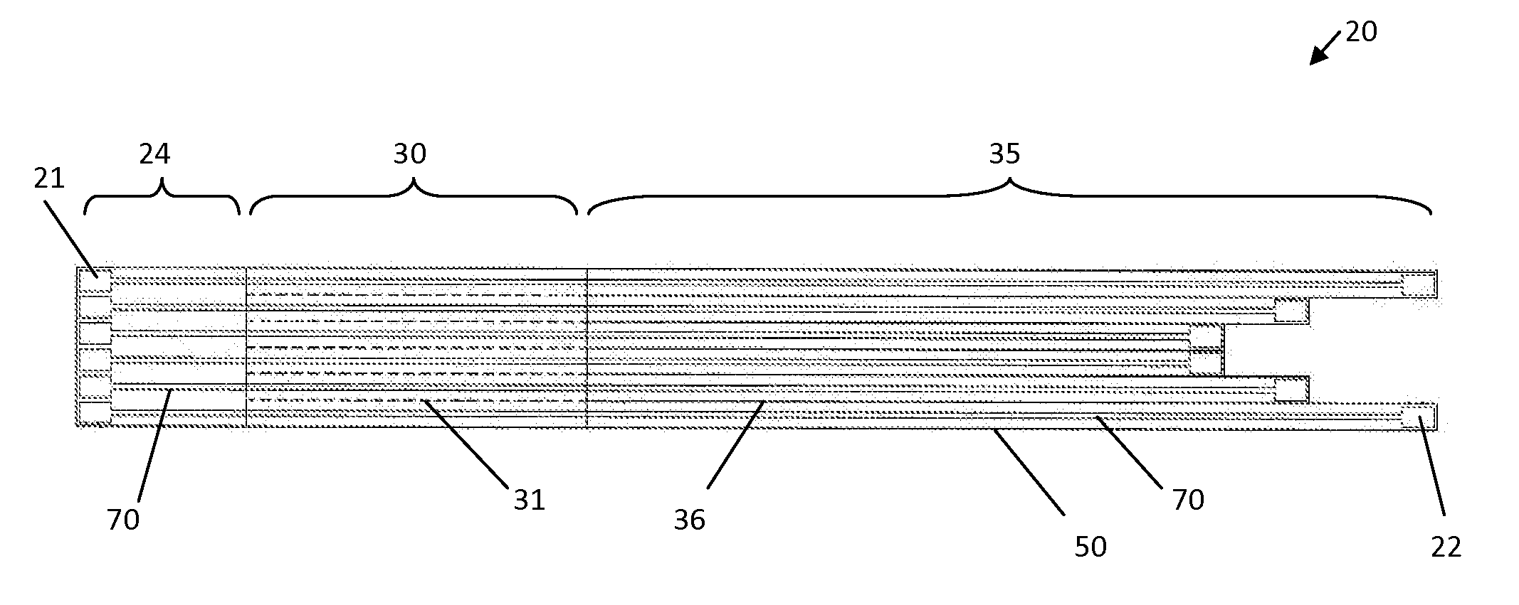
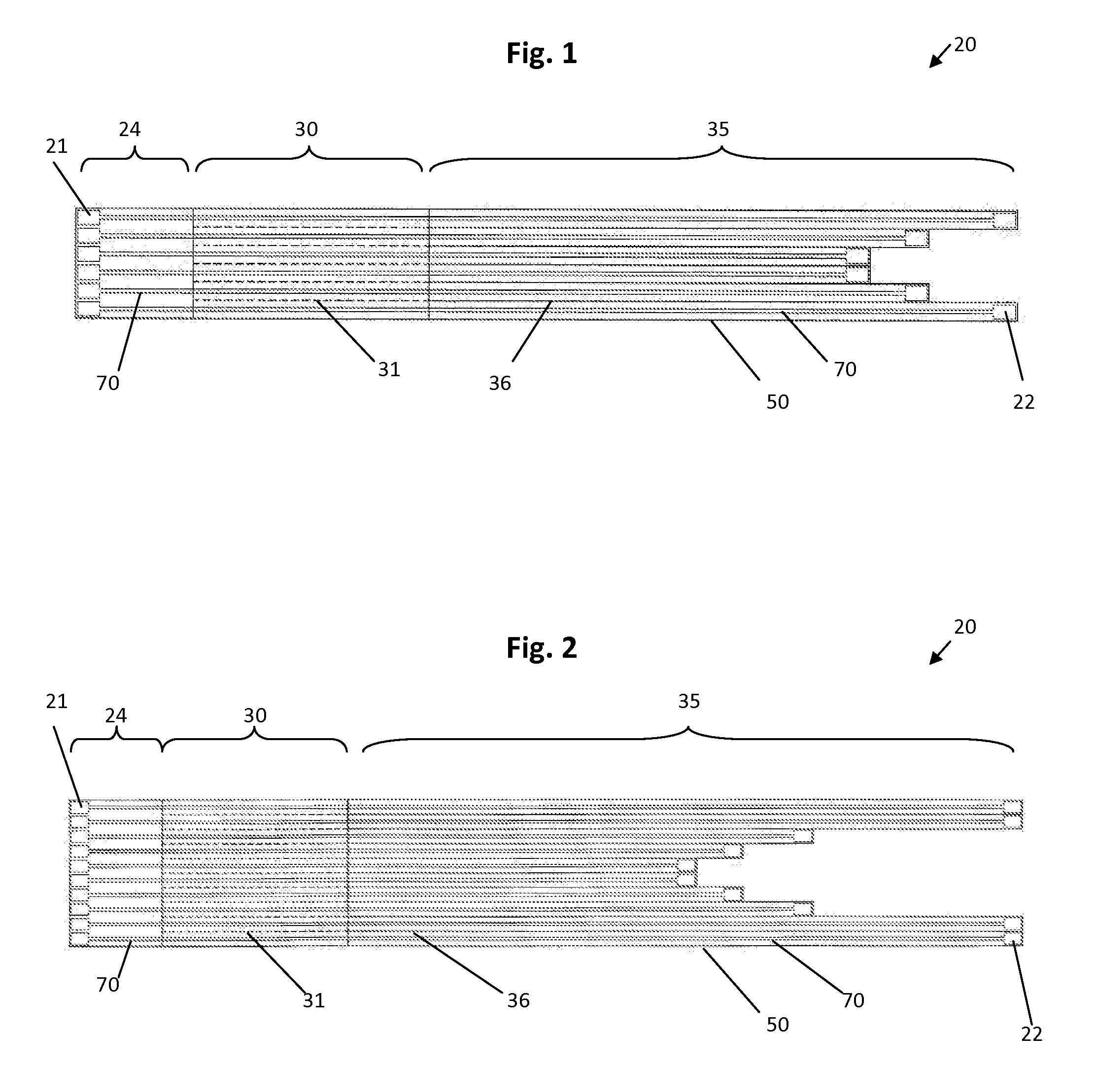
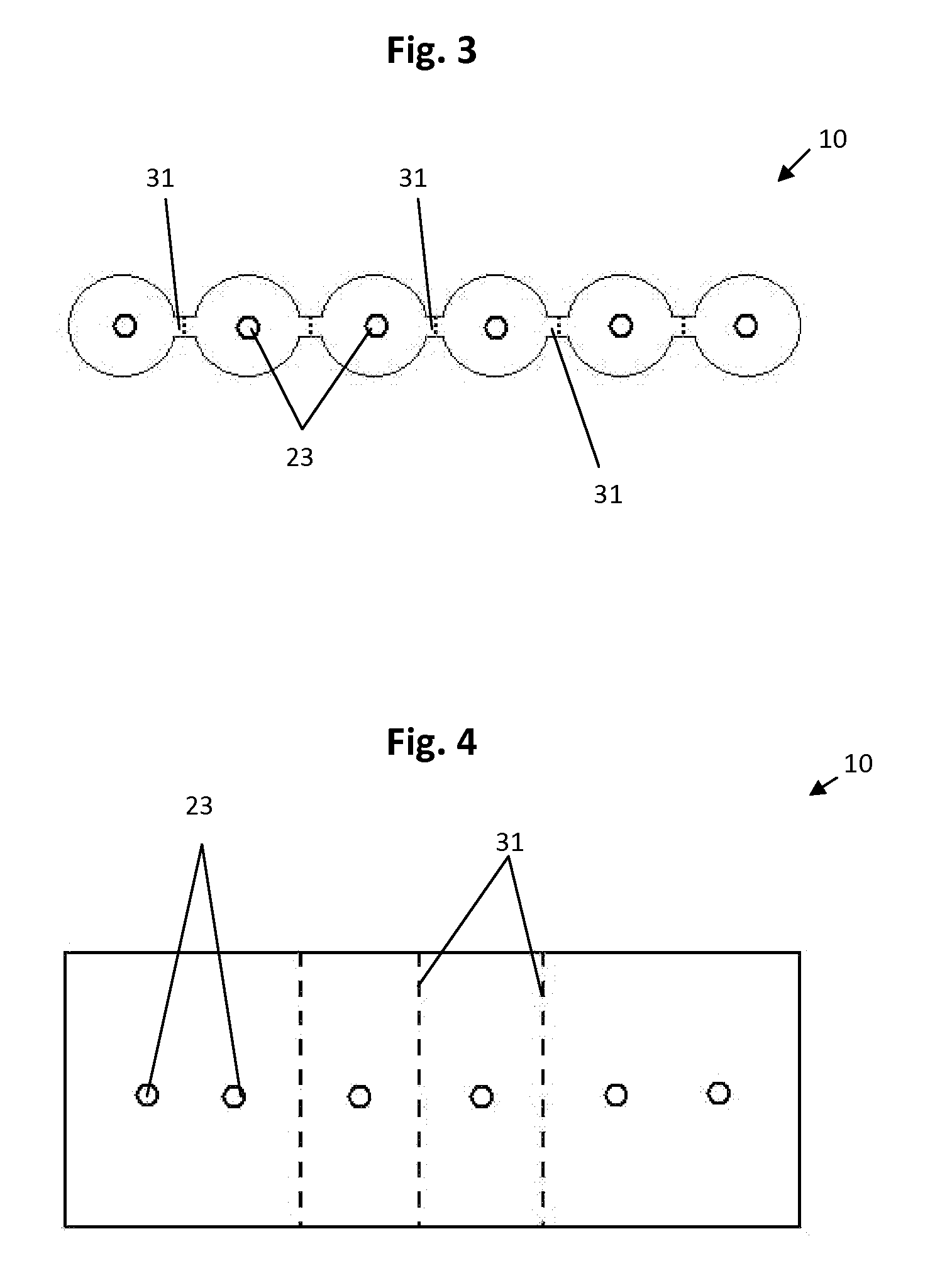
[0020]In accordance with one embodiment of the present invention, an expandable electrode pad comprising a base member, wherein the base member is composed of a stretchable material, and a plurality of distal contacts. Additional embodiment of the expandable electrode pad may further comprise a conductive circuit comprising a distal end electrically connected to the plurality of distal contacts and a proximal end comprising a plurali

Problems solved by technology

Clinicians often have difficulty connecting ECG lead sets to ECG electrodes because the individual wires of the ECG lead set often become entangled or because the clinician must determine which individual wire connects to each electrode.
In addition, the individual wires of the ECG lead sets are often long and cumbersome resulting in patient discomfort.
Issues with placement of electrodes and connection of the ECG lead set are often compounded during emergency situations.
Any delay may result in adverse consequences.
Prior art attempts have consistently failed to provide a beneficial and efficient solution to such problems.
However, a standard fixed strip of electrodes does not fit all patients due to variations in patient size, gender, weight, and other physical factors.
The devices of the prior art do not allow for movement of the electrodes to allow for proper placement on different people having varying chest sizes; do not allow for exact placement of all the electrodes; and do not allow for electrodes to be separated or placed as a one-piece unit.
The devices of the prior art also do not allow for a female person to remain wearing her undergarments while applying the electrode pad; and furthermore the devices of the prior art do not allow for “V4R” (V4R is a position on the body that is mid-clavicular over the fifth intercostal space and the R represents the patient's right side) to be obtained with the same electrode.

Method used


Image

  • Expandable Electrode Pad
  • Expandable Electrode Pad
  • Expandable Electrode Pad

Examples


Embodiment Construction

[0081]Herein is described an invention that allows for electrodes, for instance electrocardiogram electrodes but generally any medical electrode type or use including but not limited to electrocardiogram, electroencephalogram, pain relief, and muscle stimulation, to be stretched farther apart or pressed closer together as needed allowing the device to fit virtually all patients except potentially the very small. Electrodes may perform the function of detecting and transmitting electric pulses from the body surface of a patient to a unit that processes the electrical pulses; electrodes may also perform the function of transmitting electrical pulses to the body, as is done, for instance, in electrotherapy applications. The electrode pad of the present invention comprises electrodes on a base member composed of flexible and stretchy material that provides for speedy and accurate electrode placement by allowing the electrodes to be “stretched” to a desired location on the body, even rea...


PUM


Abstract

An expandable electrode pad having a flexible and stretchable base member that may be either expanded or compressed to provide proper positioning for a plurality of electrode distal contacts. Portions of the base member may have perforations that allow one or more sections of the base member to be separated and positioned a greater, non-stretchable distance away from the remaining strip of distal contacts. Additionally, the circuit body may comprise a distal cut zone that provides for freedom of movement of the plurality of distal contacts and a proximal perforated zone that eliminates lead wire entanglements while also allowing for the tearing of perforations between adjacent conductive circuits when a greater reach is required for the proper placement of a distal contact.

Description

CROSS REFERENCE TO RELATED APPLICATIONS[0001]This application claims the benefit of provisional patent application Ser. No. 61 / 237,562, filed with the USPTO on Aug. 27, 2009, which is herein incorporated by reference in its entirety.STATEMENT REGARDING FEDERALLY SPONSORED RESEARCH OR DEVELOPMENT[0002]Not applicable.INCORPORATION-BY-REFERENCE OF MATERIAL SUBMITTED ON A COMPACT DISK[0003]Not applicable.BACKGROUND OF THE INVENTION[0004]1. Field of the Invention[0005]The present invention relates to a device comprising multiple electrodes and multiple leads, particularly pads and leads for use in taking electrocardiograms wherein a plurality of electrical signals in a patient's body are monitored through his or her skin.[0006]2. Background Art[0007]Electrocardiograph (ECG) monitors and recorders are widely used to obtain biopotential signals containing information indicative of the electrical activity associated with the heart and pulmonary system. To obtain biopotential signals, ECG el...

Claims


Application Information

Patent Timeline
IPC IPC(8): A61B5/04A61B5/274
CPCA61B5/04085A61B2562/125A61B5/0416A61B5/274A61B5/282
Inventor CROSBY, WILLIAM
Owner CROSBY WILLIAM
Learn More