
Multipurpose Apparatus For Mounting Objects And Repairing Drywall

a multi-purpose, drywall repair technology, applied in the direction of walls, building repairs, construction, etc., can solve the problems of drywall damage, need repair, easy damage, etc., and achieve the effect of quick and easy separation of mounting apparatus, simple, quick and inexpensive, and non-invasiv

Inactive Publication Date: 2011-03-10
BARRY JOHN W
View PDF16 Cites 3 Cited by
  • Summary
  • Abstract
  • Description
  • Claims
  • Application Information

AI Technical Summary

Benefits of technology

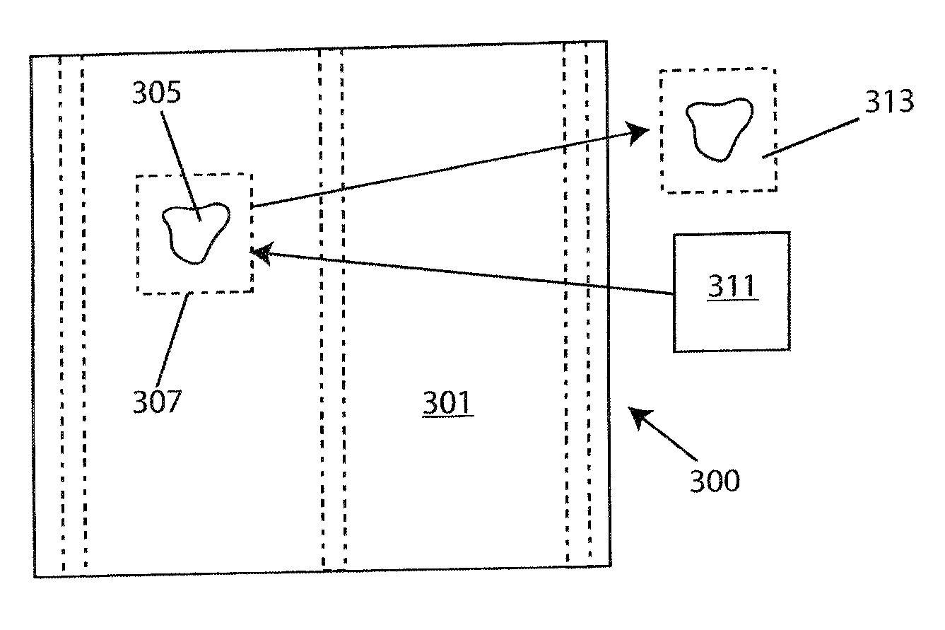
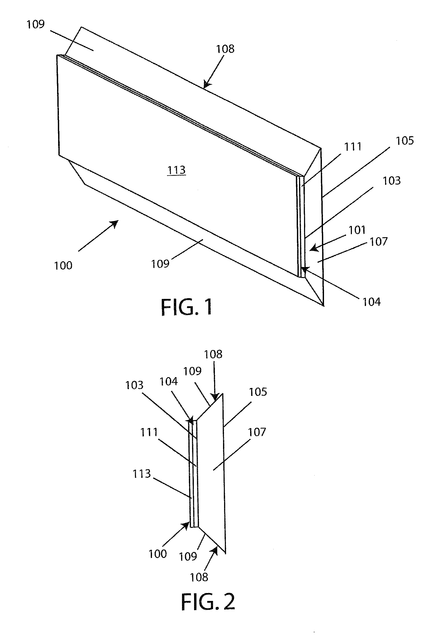
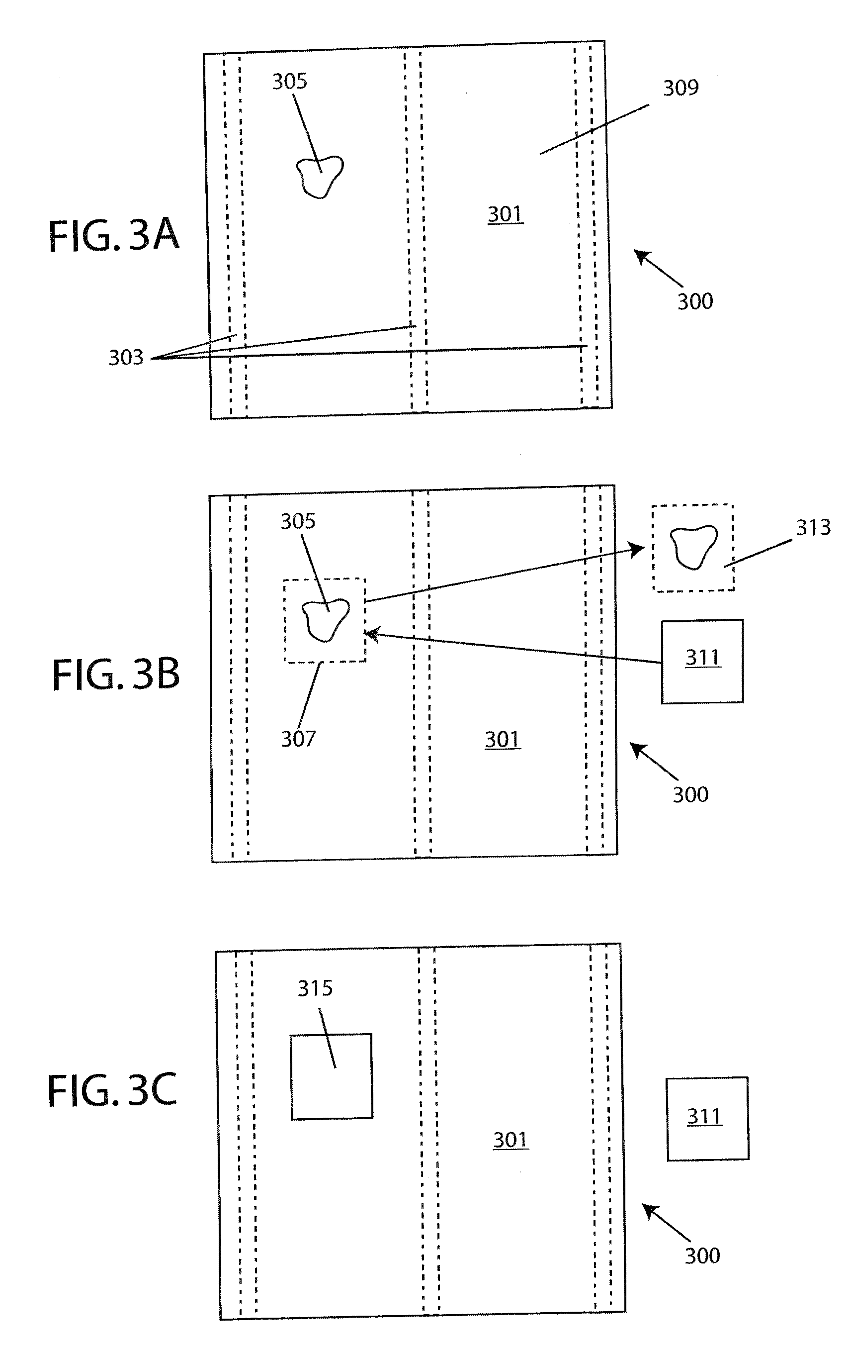
[0017]The present invention provides mounting apparatus and systems that allow for quick and easy drywall repair as well as the mounting of an object. In an exemplary embodiment of the invention, the mounting apparatus, called a Barry Stick after its inventor, comprises an elongated support member having an attaching portion for attaching the support member to a surface. The support member has a sufficient degree of rigidity to provide support to objects attached thereto. The attaching portion can include an exposable adhesive layer provided on a surface of the support member. The exposable adhesive layer may be covered by a removable protective layer which protects the exposable adhesive layer prior to use. When the mounting apparatus is ready for use, the protective layer is removed to expose the exposable adhesive layer. An exemplary embodiment of the mounting apparatus of the present invention therefore comprises: an elongated support member having a front face; an exposable adhesive layer provided atop said front face; and a removable protective layer provided atop said exposable adhesive layer.
[0020]In another exemplary embodiment of a mounting system of the present invention, multiple mounting apparatus may be used to define a receiving track for receiving another mounting apparatus. For example, a first and second mounting apparatus may be attached to a wall and arranged in a parallel-spaced-apart relationship to define a receiving track. A third mounting apparatus may be attached to an object to be mounted to the wall and the support member of the third mounting apparatus inserted into the receiving track so that the engaging surface of the inserted mounting apparatus engages the engaging surfaces of the first and second mounting apparatus. This arrangement allows for the easy mounting of an object, as well as its removal and replacement with another object by simply sliding the mounted object's mounting member along the mounting track. Of course, instead of the mounting track being defined on the wall it could be defined on the object to be mounted and the third mounting apparatus provided on the wall. In addition, multiple tracks and inserting members may be created with the mounting apparatus of the present invention and may be provided on a variety of objects and surfaces such as picture frames, plates, walls, ceilings, etc. In other exemplary embodiments of the invention, an end cap or stop may be provided to provide support at one or more ends of the track to prevent the object from sliding along the track beyond a desired position. For example, a stop may comprise a mounting apparatus that is positioned within a track defined by two spaced apart mounting members as discussed above. The stop may be fixed in a location by a variety of means, such as by inserting a fastener through one or more apertures in the stop, or by using an exposable adhesive on the stop. The stop may also be provided with one or more engaging surfaces adapted to engage the engaging surfaces of a mounting track.
[0025]Still further, the mounting member may be size adjustable. For example, the desired size of the mounting apparatus may be adjusted for the size or weight of the object to be mounted. To assist a user in obtaining a mounting apparatus of desired size the mounting apparatus may be provided with measurement indicia and perforations. For example, perforations may be provided at predetermined intervals, such as by way of example and not limitation every inch so as to assist a user in quickly and easily separating the mounting apparatus at those points. A user can place the mounting member against the object to determine a desirable size and then separate the member at the corresponding perforation or use the measurement indicia to perform measurements. As discussed above, the mounting system may also be provided with apertures for receiving nails or fasteners if desired.
[0026]The system of the present invention thus provides a simple, quick, and inexpensive method for mounting objects that requires no tools and is non-invasive when desired. The present invention allows for the mounting of a plurality of objects, and allows for the easy replacement of a mounted object. The mounting apparatus of the present invention is also capable of interior and exterior use.

Problems solved by technology

While drywall provides an aesthetically pleasing look, it is easily damaged when it is struck by an object and therefore often needs repair.
For example, drywall can be damaged when it is struck by a doorknob when opening a door or when it is struck by piece of furniture when moving the furniture.
A disadvantage of this technique is that the material generally produces a raised portion that must be heavily sanded.
Furthermore, such techniques only work for small holes and are inapplicable for larger holes because such a repair technique does not provide adequate support.
While this technique may work when there is framing located directly behind the hole that provides support for the plug, holes are often located where there is no framing on which to mount the plug.
Thus, providing sufficient support to the plug can prove difficult.
While the devices of the prior art are suited for their intended purposes, they are complex and often require special equipment.
They also often require that paper or other materials be provided atop the wall surface, thus producing an undesirable raised portion.
In addition, the prior art methods can be expensive, or limited to repairing holes of a particular size.
Furthermore, repairs by the methods of the prior art can result in a weakened area of the wall.
While it is known to mount an object to a wall using invasive hardware, such as by driving a nail into the wall to provide structure upon which to hang the picture, or screwing a bracket into the wall, such invasive mounting methods are often undesirable.
But the piercing of the wall can damage structure behind the wall such as plumbing or wiring.
In addition, the wall may be made of material, such as plaster or wood that may be susceptible to cracking or splitting when a nail is driven through it; or the material may be difficult to penetrate.
Furthermore, the use of a nail is a rather noisy process that may be inappropriate for some situations, such as when a user desires to mount an object at night when a nearby neighbor is asleep.
Finally, many prior art systems do not provide sufficient support for mounting objects on non-vertical surfaces such as ceilings or in environments in which the object may be subjected to other forces, such as wind.
In the cases where brackets are used to mount an object, it is often difficult to mate the bracket mounted on the wall to the object to be mounted.
For example, the object to be hung may lack the wire, hook, bracket, or other structure that is to be hung over the nail, thereby necessitating a complicated process by which a user must provide the object with such structure.
This may prove especially difficult in situations where the object to be mounted is not conducive to receiving such devices.
For example, it would not be possible to screw in a mounting bracket to a porcelain plate.
In addition, many bracket systems used for mounting display objects, such as commonly done with plates, at least partly cover the front surface of the object, resulting in an unappealing look that distracts from the object.
While fit for its intended purpose, the Munson Patent requires the mounting of the brackets using screws and it is not applicable to wall repair.

Method used


Image

  • Multipurpose Apparatus For Mounting Objects And Repairing Drywall
  • Multipurpose Apparatus For Mounting Objects And Repairing Drywall
  • Multipurpose Apparatus For Mounting Objects And Repairing Drywall

Examples


Embodiment Construction

[0056]Generally speaking, the apparatus, systems and methods taught herein are directed to mounting devices and systems. By applying what is taught herein, objects can quickly and easily be mounted to a desired mounting surface without the need of tools or an invasive technique. In addition, a simple and efficient method for repairing drywall is shown.

[0057]As required, exemplary embodiments of the present invention are disclosed. These embodiments are provided as examples of various embodiments of the invention and it will be understood that the invention may be embodied in alternative forms. The figures are not to scale and some features may be exaggerated or minimized to show details of particular elements, while related elements may have been eliminated to prevent obscuring novel aspects. Therefore, specific structural and functional details disclosed herein are not to be interpreted as limiting, but merely as a basis for the claims and as a representative basis for teaching one...


PUM


Abstract

A mounting apparatus includes a releasable adhesive layer and an engaging layer. In one embodiment the mounting apparatus includes an elongate support member having an attaching face comprising a removable protective layer and an adhesive layer that is exposed when the protective layer is removed. The engagable layer may include a face portion angled from the attaching face that is adapted to engage with another mounting apparatus. A system of the invention includes two spaced apart mounting apparatus that define a receiving track for receiving a mounting apparatus attached to an object to be mounted. The mounting system comprises a first engagable mounting apparatus track attachable to an object and a second track attachable to a wall. The first track and the second track cooperatively engage one another such that the object will be secured in a level orientation on the wall with the first and second tracks.

Description

CROSS REFERENCE TO RELATED APPLICATIONS[0001]This application is a division of application Ser. No. and claims the benefit of priority under 35 USC 120 of U.S. application Ser. No. 11 / 444,823, filed Jun. 1, 2006, which is a continuation-in-part of application Ser. No. 11 / 406,761, filed Apr. 19, 2006.FIELD OF THE INVENTION[0002]The present invention relates generally to mounting devices and systems. More particularly, the present invention relates to a non-invasive mounting system that may be used for a variety of applications such as repairing drywall and mounting an object to a wall.BACKGROUND[0003]Drywall, also commonly referred to as wall board or gypsum panel and commonly sold under the brand name SHEETROCK@, is often used in homes, buildings, and other structures. Drywall is essentially a chalk-like gypsum pressed between layers of paperboard. Typically, sheets of drywall are nailed or screwed to a structure's framing with a plurality of sheets “hung” next to each other in an a...

Claims


Application Information

Patent Timeline
Patent Type & Authority Applications(United States)
IPC IPC(8): E04G23/02E04B1/38
CPCE04B2002/7485E04G23/0203E04G21/10E04G23/0207
Inventor BARRY, JOHN W.
Owner BARRY JOHN W
Learn More