Cushion for mask system

a mask system and cushion technology, applied in the field of cushion for mask systems, can solve the problems of increased treatment pressure, ineffective nasal mask type patient interface, and mouth leakage,

Active Publication Date: 2011-03-10
RESMED LTD
View PDF6 Cites 120 Cited by
  • Summary
  • Abstract
  • Description
  • Claims
  • Application Information

AI Technical Summary

Benefits of technology

[0010]One aspect of the present invention relates to a mouth cushion for a mask system. The mouth cushion includes a side wall, an undercushion extending away from the side wall, and a membrane provided to substantially surround the undercushion and adapted to form a continuous seal around an exterior of a patient's mouth in use. The side wall includes spaced-apart prong support structures that provide annular recesses adapted to support respective nasal prongs. Each prong support structure includes an alignment indicator to aid correct assembly of the respective nasal prong.

Problems solved by technology

A number of patients thus find that during sleep when muscles relax, mouth leak may occur.
Alternatively, some patients are naturally mouth breathers and thus find a nasal mask type patient interface ineffective.
Mouth leak is undesirable as, among other difficulties, it may result in noise, increased treatment pressure to compensate for the leak or an increased load on the nasal passages and potentially nasal obstruction or a runny nose.
Leak is a problem common to all designs of patient interface.
Typically, this is not achieved for the entire range of patients and some form of leak occurs.
The problem is heightened during sleep when the jaw moves and the head position changes.
This action can often serve to dislodge the mask and cause leak.
Since leak can be noisy and results in less-effective treatment, users often compensate by tightening the headgear more than is desired.
This is detrimental for patient comfort and can cause skin breakdown or irritation.
A further problem encountered by patients who are using full face, nasal or nose and mouth masks is that the portion of the patient interface that seals around the nasal bridge prevents the patient from wearing spectacles.
Additionally, it may give the sensation of being closed in, leading to a feeling of claustrophobia, particularly when combined with a mouth-sealing portion.
A further disadvantage is that any leaks that may occur can affect the sensitive area surrounding the eyes.

Method used


Image

  • Cushion for mask system
  • Cushion for mask system
  • Cushion for mask system

Examples


first embodiment

1.1 First Embodiment of Mouth Cushion

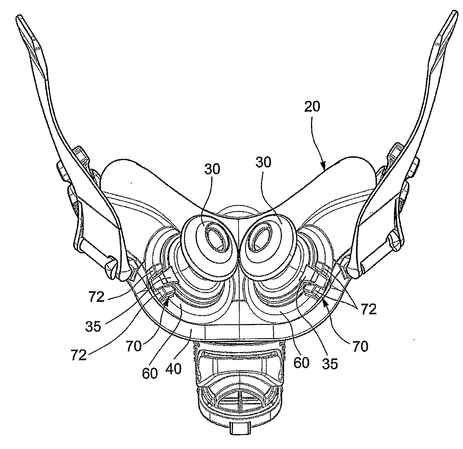
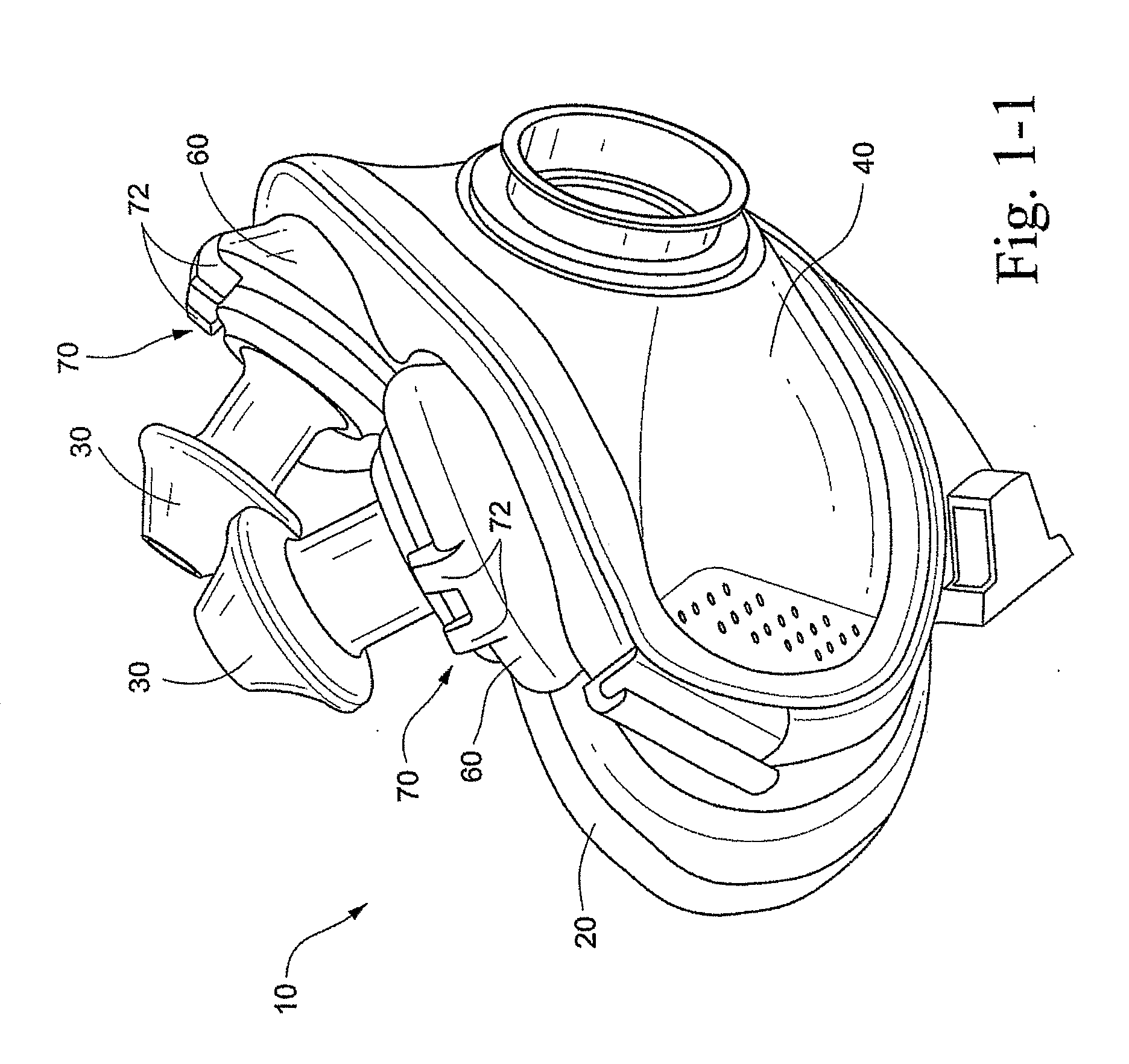
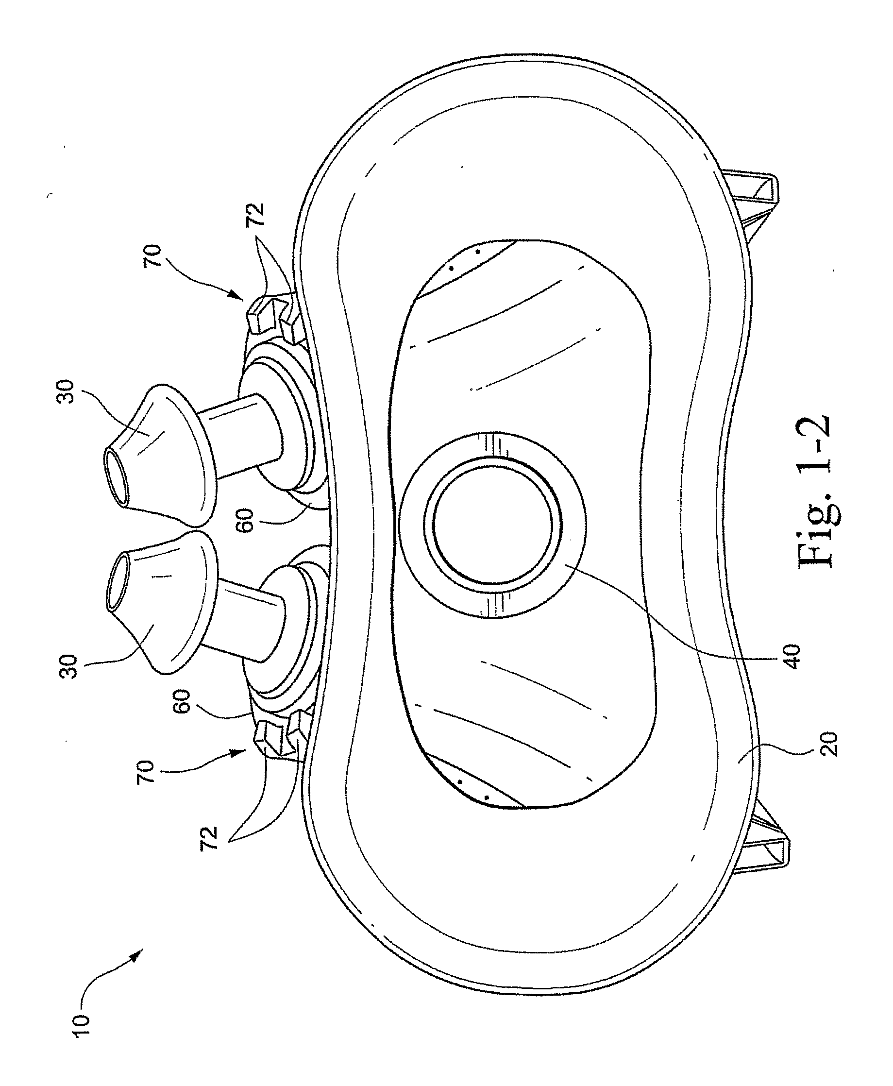
[0035]FIGS. 2-1 to 2-7 illustrate the mouth cushion 20 of the sealing assembly according to an embodiment of the present invention. As illustrated, the mouth cushion 20 includes a face-contacting portion 22 and a non-face-contacting portion 24.

[0036]As best shown in FIGS. 2-6 and 2-7, the face-contacting portion 22 of the cushion 20 includes a side wall 50, an undercushion 52 extending away from the side wall 50, and a membrane 54 provided to substantially surround the undercushion 52 and provide a sealing structure for the face-contacting portion 22. The inner edge of the membrane 54 defines an aperture 57 that receives the patient's mouth (see FIGS. 2-1 and 2-3).

[0037]The non-face-contacting portion 24 is structured to be removably and replaceably attached to the frame 40. As best shown in FIGS. 3-1 and 3-2, the frame 40 includes a main body 44 having a side frame portion 46 on each lateral side thereof. The main body 44 includes an aperture 45...

second embodiment

1.2 Second Embodiment of Mouth Cushion

[0050]FIGS. 4-1 to 4-3 illustrate a cushion 220 according to another embodiment of the present invention. In this embodiment, no arcuate configuration is provided over a short distance at the upper lip and lower lip sections UL, LL of the cushion profile. The arcuate configuration is provided at the sides of the cushion 220, which then slowly blends to a flat configuration over a short distance at the top and bottom lip sections.

[0051]Specifically, as shown in FIG. 4-2, the side wall 250, undercushion 252, and membrane 254 at the upper lip and lower lip sections UL, LL are all generally aligned in a relatively straight profile. As shown in FIG. 4-3, the lower portion of the undercushion 252 at the cheek sections C has a more arcuate, e.g., semi-circular, question-mark, sickle-shape, configuration that provides greater flexibility to the undercushion 252 in use.

[0052]The combination of the arcuate configuration at the cheek sections C and a steep...

third embodiment

1.4 Third Embodiment of Mouth Cushion

[0057]FIGS. 6-1 to 6-3 illustrate a cushion 320 according to another embodiment of the present invention. In this embodiment, each side of the cushion 330 includes a support strut or rib 325. As illustrated, the support strut 325 extends generally horizontally along an exterior surface of the respective side of the cushion 320. In use, the support strut 325 may modify the deflection characteristic of the cushion 320. It should be appreciated that the support strut 325 may have other suitable shapes, arrangements, and positioning along the cushion 320 to modify the deflection characteristic. In addition, one or more support struts may be provided to modify the deflection characteristic.

1.5 Alternative Embodiments of Mouth Cushion

[0058]FIG. 8-1 illustrates a cross-section of a mouth cushion 420 according to an alternative embodiment of the present invention. As illustrated, the cushion cross-section includes a side wall 450, undercushion 452, and m...


PUM


Abstract

A mouth cushion for a mask system includes a side wall, an undercushion extending away from the side wall, and a membrane provided to substantially surround the undercushion and adapted to form a continuous seal around an exterior of a patient's mouth in use. The side wall includes spaced-apart prong support structures that provide annular recesses adapted to support respective nasal prongs, and at least a portion of the undercushion includes a question-mark or sickle-shape configuration when in cross-section.

Description

CROSS-REFERENCE TO APPLICATIONS[0001]This application claims the benefit of U.S. Provisional Application No. 60 / 848,360, filed Oct. 2, 2006, which is incorporated herein by reference in its entirety.[0002]Also, PCT Application No. PCT / AU2006 / 000770, filed Jun. 6, 2006, and U.S. application Ser. No. 11 / 447,295, filed Jun. 6, 2006, are each incorporated herein by reference in its entirety.FIELD OF THE INVENTION[0003]The present invention relates to a cushion for a mask system used for treatment, e.g., of Sleep Disordered Breathing (SDB) with Continuous Positive Airway Pressure (CPAP) or Non-Invasive Positive Pressure Ventilation (NIPPV).BACKGROUND OF THE INVENTION[0004]Mask systems form an interface between a patient and apparatus providing a supply of pressurized air or breathing gas and are hence sometimes referred to as patient interfaces. In this specification, the words mask system and patient interface may be used interchangeably. Mask systems in the field of the invention diffe...

Claims


Application Information

Patent Timeline
Patent Type & Authority Applications(United States)
IPC IPC(8): A61M16/08
CPCA61M16/0666A61M2205/6045A61M16/06A61M16/0683A61M16/0622A61M16/0611A61M2210/0625A61M16/0616
Inventor SCHEINER, RUPERT CHRISTIANHOWARD, SCOTT ALEXANDERSMART, GREGORY SCOTTSKIPPER, CHRISTOPHER SCOTTLUBKE, STEVEN JOHNNELSON, TIMOTHY SHAWN
Owner RESMED LTD
Why Eureka
Try Eureka