
Pressure Relief Valve for a Vehicle Body

a pressure relief valve and vehicle body technology, applied in ventilation systems, heating types, lighting and heating apparatuses, etc., can solve problems such as door closing, noise-making flaps of relief valves, and deterioration of flap types, so as to avoid the use of noisy flaps

Inactive Publication Date: 2011-03-10
GM GLOBAL TECH OPERATIONS LLC
View PDF6 Cites 29 Cited by
  • Summary
  • Abstract
  • Description
  • Claims
  • Application Information

AI Technical Summary

Benefits of technology

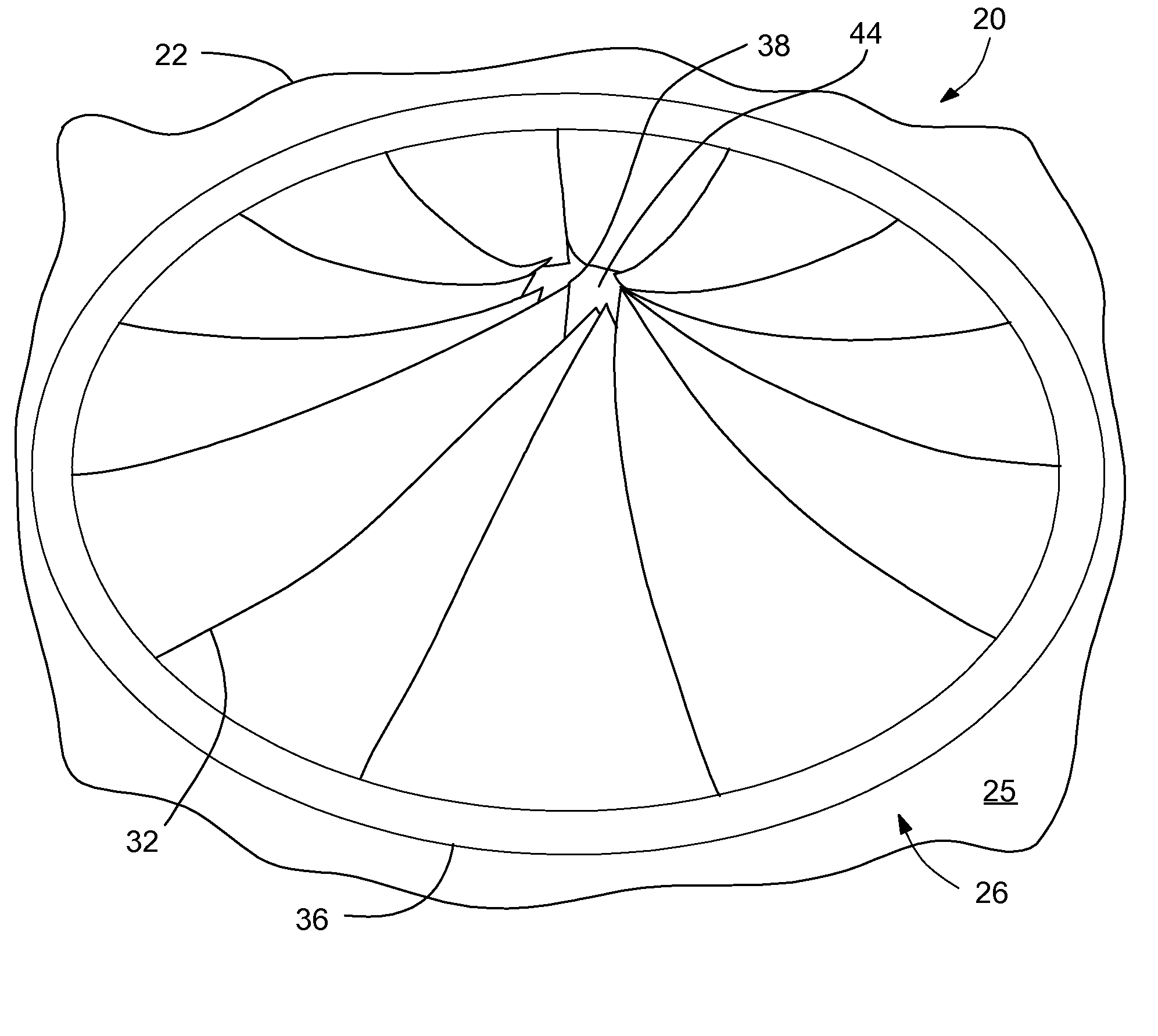
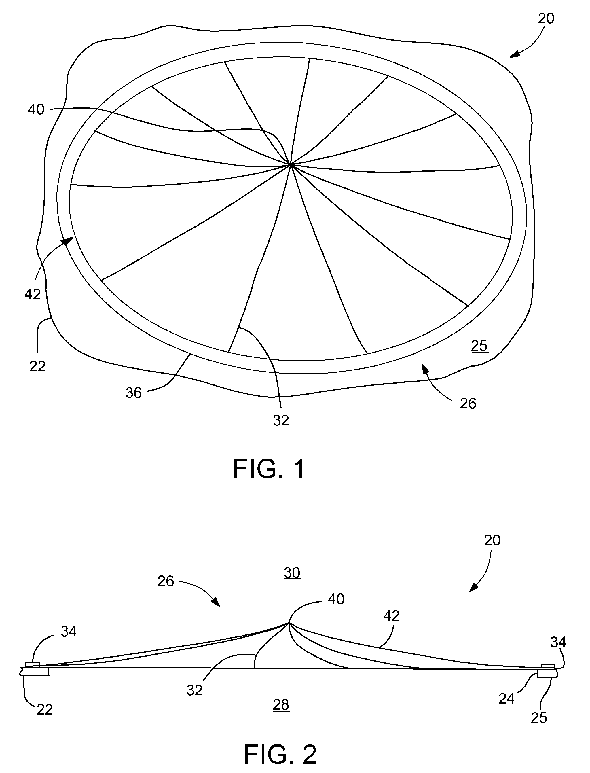
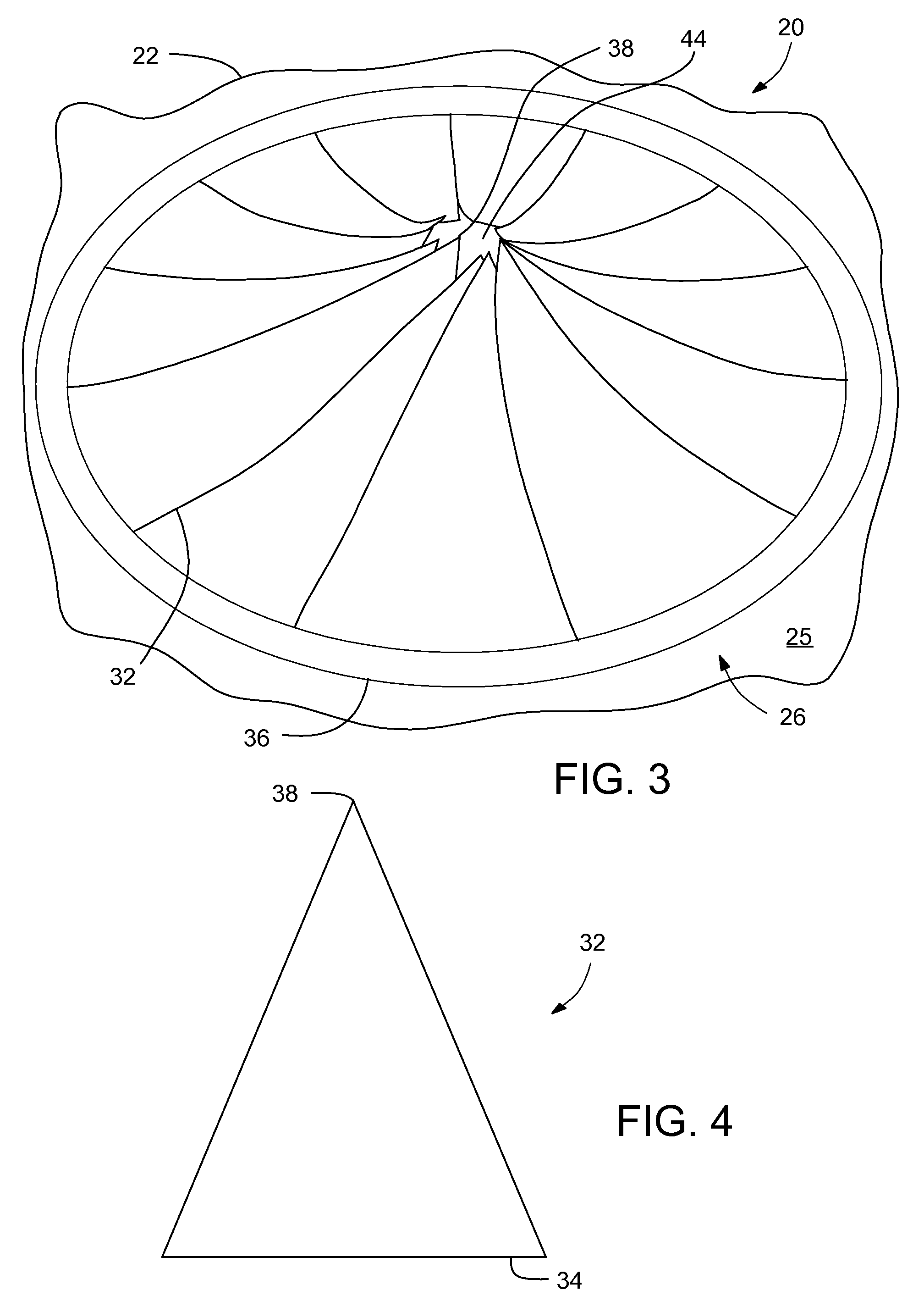
The patent describes a pressure relief valve for automotive vehicles that can relieve air pressure from the interior of the vehicle to the outside. The valve consists of flexible interleaved flaps that cover a body opening and are secured to the valve mounting location. The flaps are designed to flex and create a central opening when the air pressure in the vehicle interior exceeds the outside pressure. The valve can be mounted at various angles and can be modified to accommodate different body openings. The technical effects of this invention include achieving desired one-way air flow, avoiding noisy flaps, and being adaptable to various vehicle shapes.

Problems solved by technology

Some pressure relief valves currently in use are sensitive to mounting angle on the vehicle body and may sometimes hang open, allowing water, dust, noise and air intrusion into the vehicle interior.
Moreover, many pressure relief valves have flaps that make noise during door closing and rough road events because the pivoting flaps bounce against a plastic frame.
In addition, these types of flaps may deteriorate over time, with the edges curling, creating a constant open air pathway into the vehicle interior.
One possible solution is to use rubber flaps rather than plastic flaps, but these are more expensive than desirable for many vehicles.

Method used


Image

  • Pressure Relief Valve for a Vehicle Body
  • Pressure Relief Valve for a Vehicle Body
  • Pressure Relief Valve for a Vehicle Body

Examples


second embodiment

[0024]FIGS. 5-7 illustrate a Since this embodiment is similar to the first, similar element numbers will be used for similar elements, but employing 100-series numbers. In this embodiment, the body opening 124 in the vehicle body structure 122 is not circular anymore, thus the pressure relief assembly 120 is changed to accommodate this. Irregular shaped body openings 124 may be needed on some vehicles due to vehicle packaging constraints, and the pressure relief assembly 120 can be shaped to accommodate these constraints while still providing the desired pressure relief. Thus, although only two shapes of pressure relief assemblies are shown in the two embodiments herein, those skilled in the art will appreciate that the pressure relief assembly may be formed in many different shapes to accommodate vehicle packaging requirements.

[0025]In this embodiment, individual flaps 132 may have different shapes to accommodate the shape of the body opening 124. For example, FIG. 6 illustrates a...

first embodiment

[0026]The operation of the pressure relief valve 126 in this embodiment is essentially the same as in the first embodiment and so will not be discussed further.


PUM


Abstract

A pressure relief valve for relieving air pressure from an automotive vehicle interior. The pressure relief valve mounts on a valve mounting location that surrounds a body opening and includes flexible interleaved flaps and a securing mechanism. The flaps cover the body opening, with each of the flaps being generally triangular in shape and having an outer end adjacent to the valve mounting location and a pair of sides extending from the outer end inward to an inner corner, with the inner corners meeting to form a peak. The interleaved flaps form a generally pyramidal-shape that angles away from the automotive vehicle interior as the interleaved flaps extend inward from the outer ends toward the peak. The securing mechanism is secured to the radially outer ends of the flaps and to the valve mounting location.

Description

BACKGROUND OF INVENTION[0001]The present invention relates generally to a control and pressure relief valve for relieving pressure from an automotive vehicle interior to atmospheric pressure outside the vehicle interior.[0002]Automotive HVAC systems provide cooled or heated pressurized air to automotive vehicle interiors. Typically, pressure relief valves are included in the vehicle body to relieve pressure from within the vehicle interiors during operation of the HVAC system to control air flow in the automotive vehicle interiors and keep the automotive interior pressure and atmospheric pressures substantially balanced. These pressure relief valves also allow for pressure relief from the vehicle interiors when a door, deck lid or the like is closed to reduce the door closure effort. The valves are also designed to keep dirt, water and fumes out of the vehicle interiors by preventing air flow back through the valve into the vehicle interior.[0003]Some pressure relief valves currentl...

Claims


Application Information

Patent Timeline
Patent Type & Authority Applications(United States)
IPC IPC(8): F16K17/02
CPCB60H1/249F24F11/043F16K15/147F24F11/745Y10T137/0396Y10T137/7879
Inventor CHAMBO, KIMBERLY A.TAHNOOSE, MARC J.
Owner GM GLOBAL TECH OPERATIONS LLC
Learn More