Monitor Device, Switching Device, TV System, and Display Method

Inactive Publication Date: 2011-03-10
KK TOSHIBA
View PDF1 Cites 4 Cited by
  • Summary
  • Abstract
  • Description
  • Claims
  • Application Information

AI Technical Summary

Problems solved by technology

However, in such case, an external input sour

Method used


Image

  • Monitor Device, Switching Device, TV System, and Display Method
  • Monitor Device, Switching Device, TV System, and Display Method
  • Monitor Device, Switching Device, TV System, and Display Method

Examples


embodiment 1

[0018]A first embodiment will be described below with reference to FIGS. 1-6.

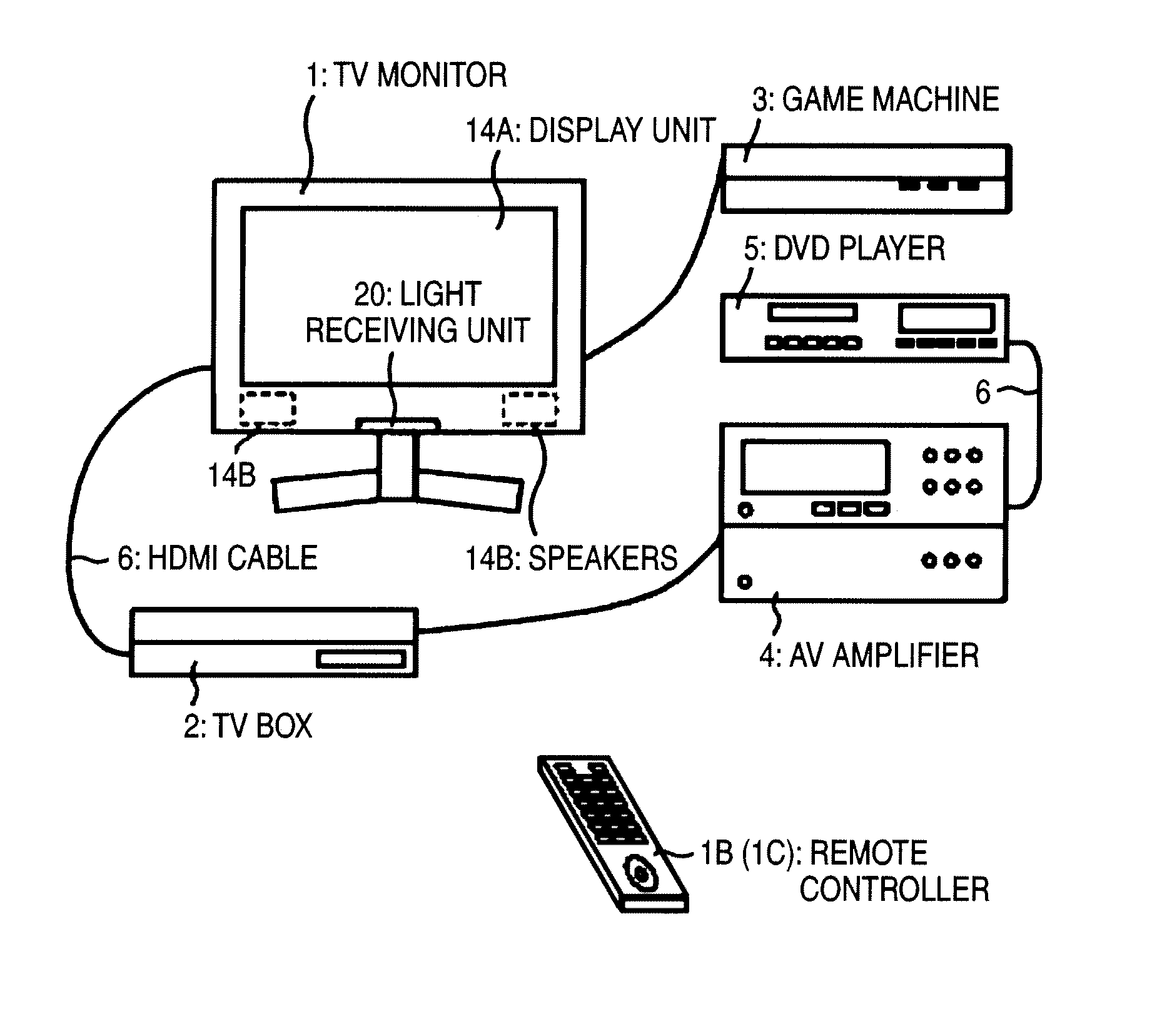
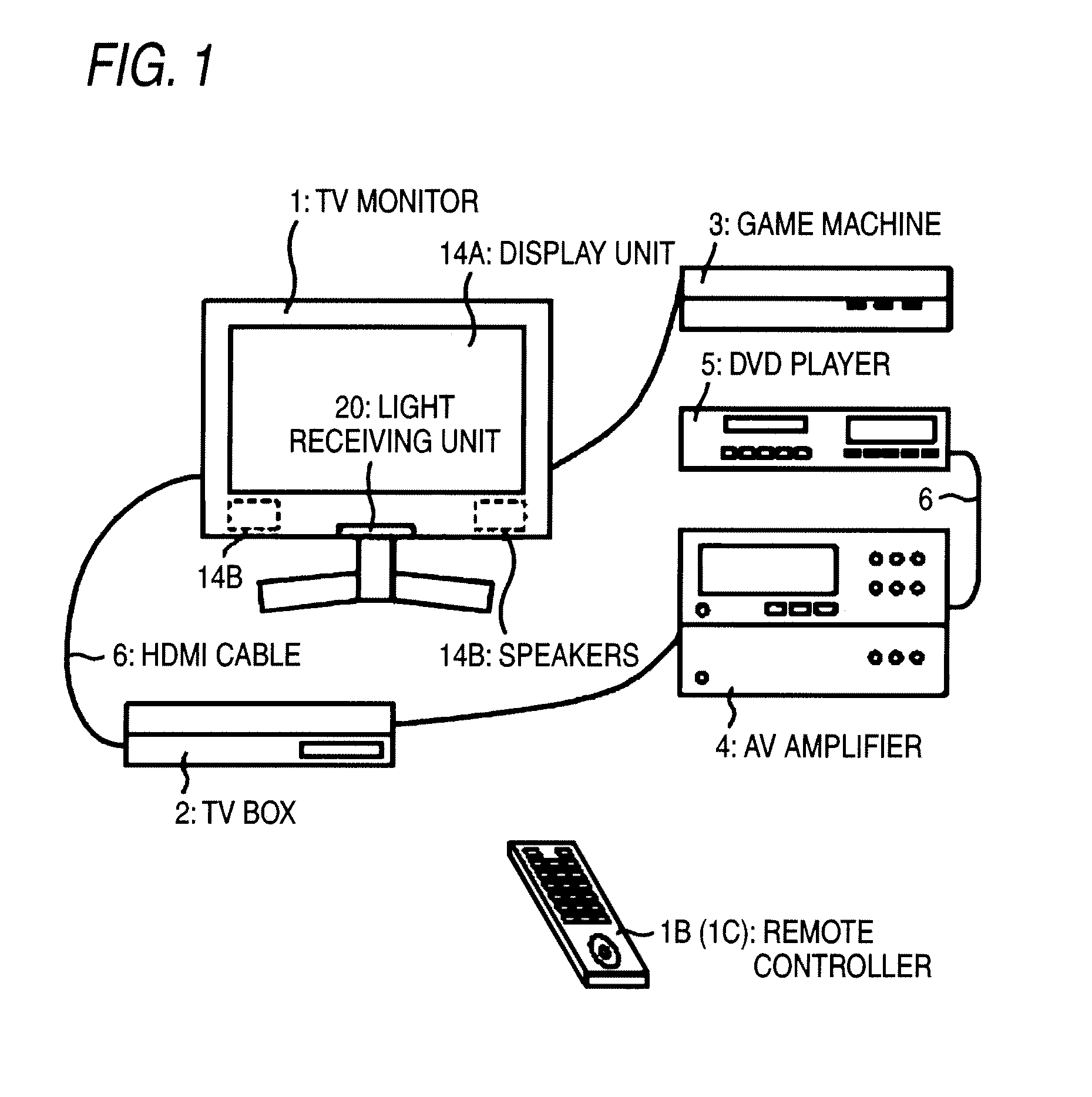
[0019]FIG. 1 illustrates a TV system in which a TV monitor as a screen display unit and a TV box 2 as a broadcast receiving unit are separated from each other. The TV monitor 1 and the TV box 2 are connected to each other by a cable or a wireless communication. Each of the TV monitor 1 and the TV box 2 has plural external input terminals to each of which an external device is connected. In the system of FIG. 1, the TV monitor 1 and the TV box 2 are connected to each other by an HDMI (high-definition multimedia interface) cable 6.

[0020]The system includes the TV monitor 1 and the TV box 2 which are electronic apparatus for receiving, demodulating, and displaying a terrestrial digital broadcast or a satellite broadcast such as a BS (broadcast satellite) or CS (communication satellite) broadcast via an antenna or receiving and displaying video signal supplied from an external input source, and a DVD player 5 f...

embodiment 2

[0047]A second embodiment will be described below with reference to FIG. 1 to FIGS. 7A and 7B. Sections, units, etc. having the same ones in the first embodiment will not be described in detail.

[0048]FIGS. 7A and 7B partially illustrate a system according to the second embodiment. The TV box 2 shown in FIG. 1 is divided into a box 22 and a tuner 23. Although not shown, the antenna 1A is connected to the tuner 23. The box 22 and the tuner 23 are connected to each other via an HDMI cable. The box 22 is provided with a switching module (not shown) which receives an instruction to switch input source transmitted from the TV monitor 1, and switches between input sources according to the received instruction.

[0049]In the example of FIG. 7A, the box 22 and the tuner 23 correspond to the TV box 2. In the example of FIG. 7B, a box 22c is provided upstream of the TV monitor 1 (the box 22c is provided between the TV monitor 1 and the box 22 and the boxes 22 and 22c are connected to each other ...


PUM


Abstract

According to an aspect of the present invention, there is provided a monitor device including: a first port configured to receive videos output from an external switching device, the external switching device being connected to first input sources; a second port configured to receive a video output from an external source device as a second input source; and a display module configured to display: information about the first input sources, as a group, obtained through the external switching device; and information about the second input source, as a port name of the second port and/or apparatus information about the external source device, obtained from the external source device, wherein a switching operation between the first input sources and the second input source is performed in accordance with a switching instruction sent from an external manipulation device having a button to perform the switching operation.

Description

CROSS-REFERENCE TO RELATED APPLICATIONS[0001]This application is based upon and claims the benefit of priority from Japanese Patent Application No. 2009-207805, filed on Sep. 9, 2009, the entire contents of which are incorporated herein by reference.BACKGROUND[0002]1. Field[0003]An aspect of the present invention relates to a TV system and, more particularly, to an external input switching method.[0004]2. Description of the Related Art[0005]Generally, the liquid crystal monitors require small occupation space and low power consumption. In recent years, with the reduction in their prices, liquid crystal monitors have spread rapidly as monitors of desktop personal computers. Liquid crystal monitors gained a position as a display device to succeed CRT displays so as to be close to ordinary consumers. Not only have liquid crystal monitors come to be used as PC monitors but also their use as TV receivers has increased widely by virtue of their style. For example, TV receivers have been p...

Claims


Application Information

Patent Timeline
IPC IPC(8): H04N5/268H04N7/18
CPCA63F2300/203H04N21/43615H04N5/44G09G5/006
Inventor IDA, TOMOTAKA
Owner KK TOSHIBA
Why Eureka
Try Eureka