Inspecting Device

a technology of inspection device and mirror, which is applied in the field of inspection device, can solve the problems of easy damage of mirror b>40/b>, the conventional inspection device suffers, etc., and achieves the effect of reliable inspection

Inactive Publication Date: 2011-03-10
CHI MARK PRECISION IND CORP +1
View PDF1 Cites 41 Cited by
  • Summary
  • Abstract
  • Description
  • Claims
  • Application Information

AI Technical Summary

Benefits of technology

[0006]It is an objective of the present inven

Problems solved by technology

The conventional inspecting device however suffers some disadvantages.
Secondly, the mirror 40 can easily be damaged w

Method used


Image

  • Inspecting Device
  • Inspecting Device
  • Inspecting Device

Examples


Embodiment Construction

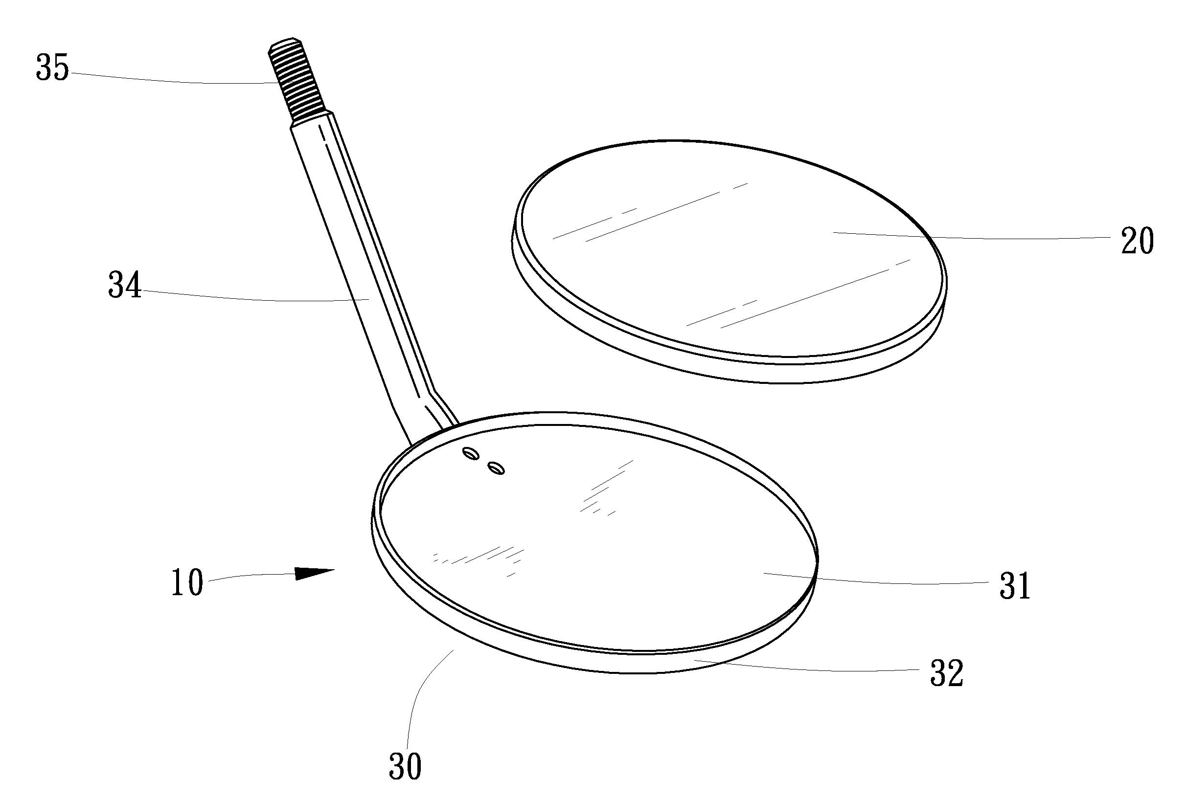
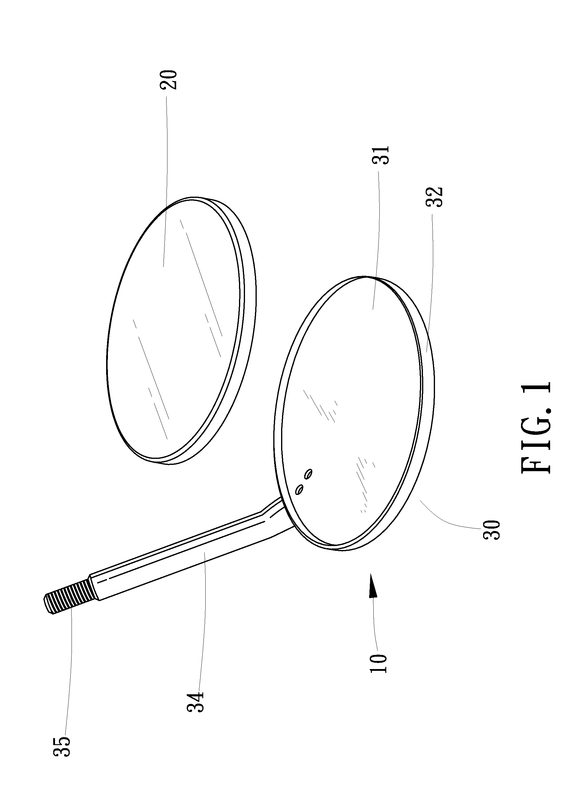
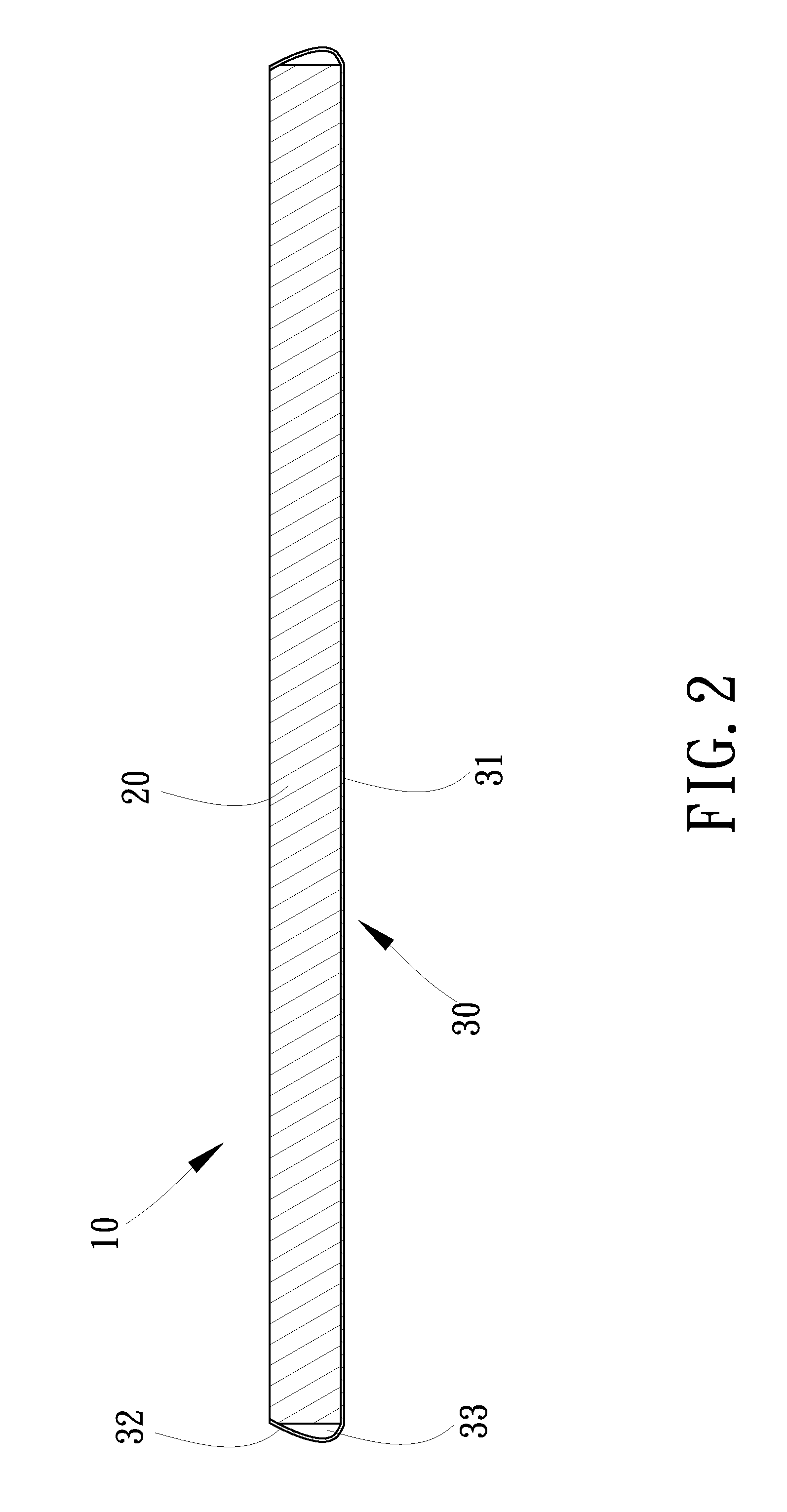
[0016]Referring to FIGS. 1 and 2, an inspecting device 10 includes a mirror 20, a frame 30 and a shank 34 according to a first embodiment of the present invention. The frame 30 includes a back plate 31 and a rim 32 formed on and around the back plate 31. The back plate 31 is shaped corresponding to the mirror 20. The area of the back plate 31 is larger than that of the mirror 20. The rim 32 extends from the back plate 31 and converges. Thus, the periphery of the mirror 20 is firmly held with the rim 32 of the frame 30. There is a buffering space 33 defined between the periphery of the mirror 20 and the rim 32 of the frame 30. The buffering space 33 is intended to protect the mirror 20 when the frame 30 is hit during operation.

[0017]The shank 34 is an angled element. An end of the shank 34 is connected to the back plate 31 of the frame 30 by welding or a rivet for example. Another end of the shank 34 is formed with a thread 35. The thread 35 of the shank 34 can be engaged with a thre...


PUM


Abstract

An inspecting device is used in limited space. The inspecting device includes a mirror and a frame. The frame includes a back plate and a rim extending from the back plate and converging. Thus, the periphery of the mirror is firmly held with the rim of the frame. Moreover, a buffering space is defined between the periphery of the mirror and the rim of the frame.

Description

BACKGROUND OF INVENTION[0001]1. Field of Invention[0002]The present invention relates to an inspecting device for use in limited space.[0003]2. Related Prior Art[0004]Referring to FIG. 5, there is shown a conventional inspecting device for use in limited space. The conventional inspecting device includes a mirror 40, a back plate 41 and an adhesive layer 42 for attaching the mirror 40 to the back plate 41. The back plate 41 is connected to a shank operable to maneuver the mirror 40. Thus, the conventional inspecting device can be used to inspect the interior of a vehicle, machine or mouth. The conventional inspecting device however suffers some disadvantages. Firstly, the mirror 40 can easily be detached from the back plate 41 because of inadequate provision of the adhesive layer 42 or deterioration of the adhesive layer 42 caused by heat. Secondly, the mirror 40 can easily be damaged when it is used to inspect the interior of a vehicle or machine since the periphery of the mirror 4...

Claims


Application Information

Patent Timeline
IPC IPC(8): G02B7/182
CPCA61B1/247A45D42/00
Inventor SU, CHEN-CHIN
Owner CHI MARK PRECISION IND CORP
Why Eureka
Try Eureka