
USB based expresscard device

a technology of expresscard and usb, applied in the direction of coupling device connection, electrical apparatus casing/cabinet/drawer, instruments, etc., can solve the problems of increasing the height of the device, complicated circuit layout, etc., and achieve the effect of avoiding accidental impact damag

Inactive Publication Date: 2011-03-10
D&C TECH
View PDF5 Cites 4 Cited by
  • Summary
  • Abstract
  • Description
  • Claims
  • Application Information

AI Technical Summary

Benefits of technology

[0007]The present invention has been accomplished under the circumstances in view. It is one object of the present invention to provide a USB3.0 based ExpressCard device, which has a USB3.0 connector be incorporated into an ExpressCard together without increasing the dimension of the ExpressCard, avoiding accidental impact damage.
[0009]Further, the metal shield of the USB3.0 connector can be formed of two symmetrical halves that are respectively formed integral with the top and bottom cover shells of the ExpressCard, facilitating installation.
[0010]Further, after installation of the USB3.0 connector in the opening in the front locating shell of the electrically insulative bracket of the ExpressCard, the USB3.0 does not protrude over the front side of the ExpressCard, thus the length and width of the USB based ExpressCard device are maintained equal to the length and width of the ExpressCard. Therefore, the USB based ExpressCard device can be completely inserted into the ExpressCard slot of an electronic apparatus, avoiding accidental impact damage.

Problems solved by technology

Subject to the limitations of data transmission speed and power supply stability, this design of USB based ExpressCard device is simply suitable for use in a low transmission speed peripheral apparatus (such as card reader, printer, mobile disk drive, internet telephone or webcam), not practical for use in a high capacity hard disk drive, DVD copier, DVD player, blue light DVD copier or blue light DVD player.
Either of the two methods complicates the circuit layout and increases the device height.
The part of the USB3.0 based ExpressCard device that protrudes out of the peripheral wall of the notebook computer may be impacted by an external object accidentally, causing damage.

Method used


Image

  • USB based expresscard device
  • USB based expresscard device
  • USB based expresscard device

Examples


Embodiment Construction

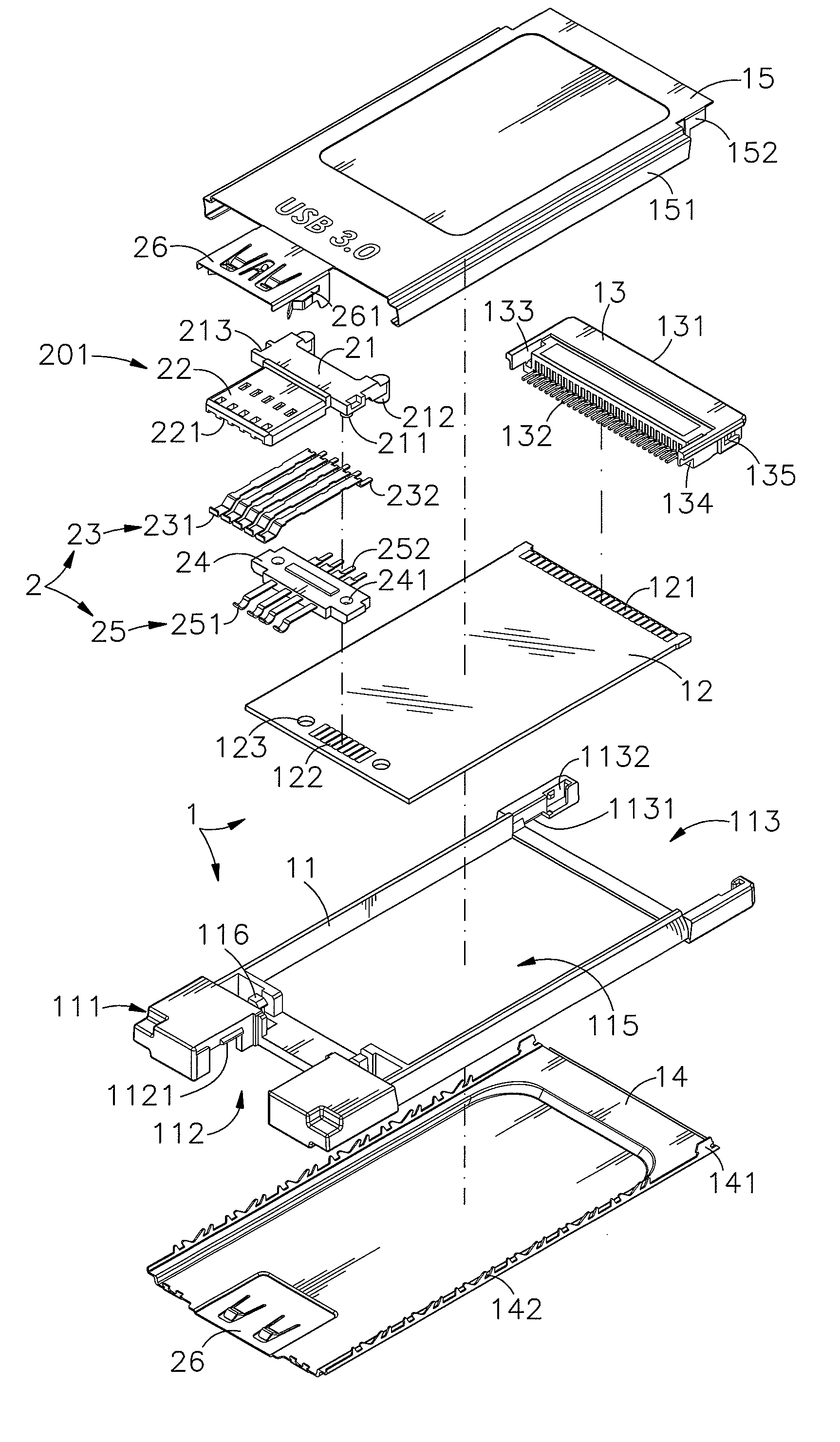
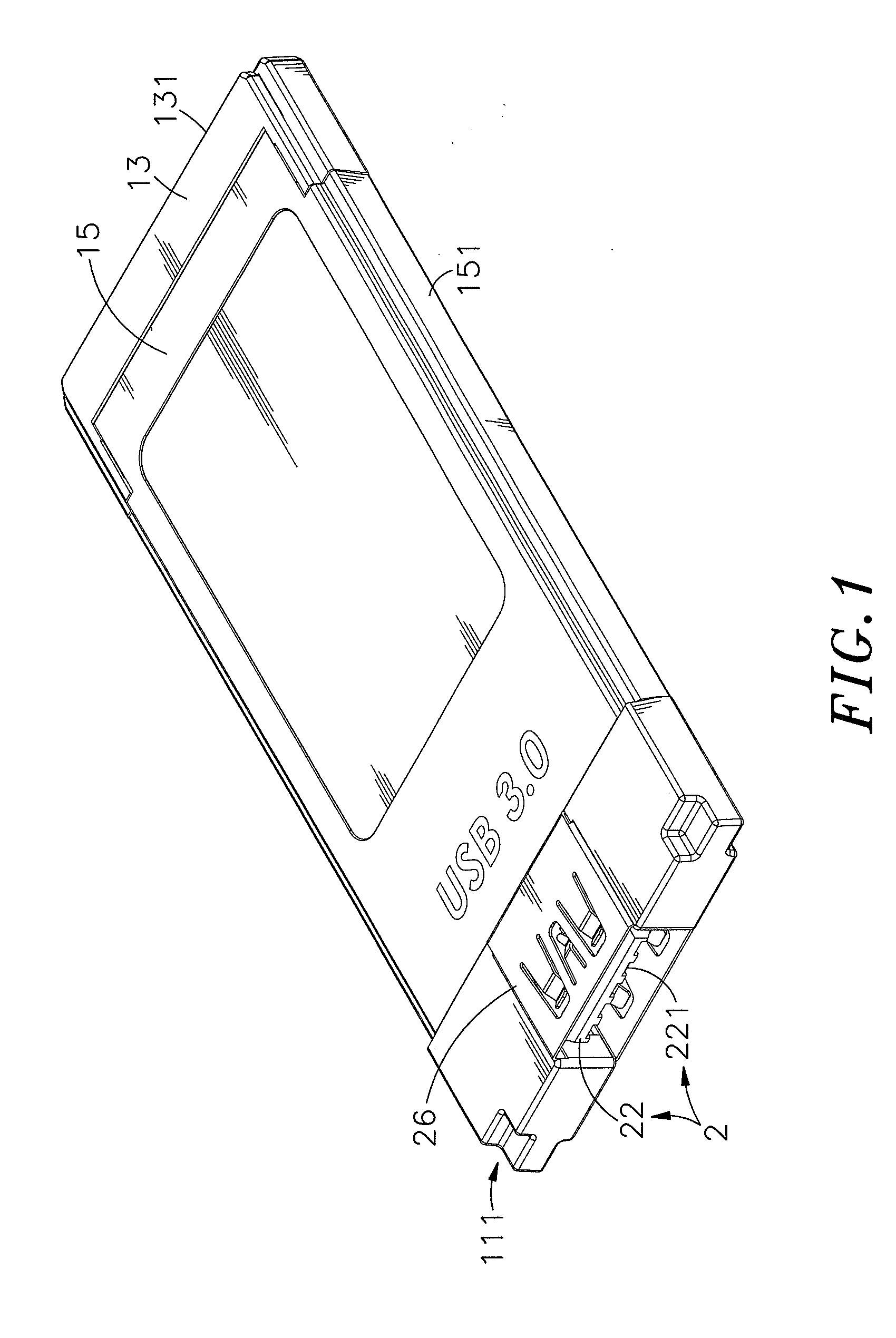
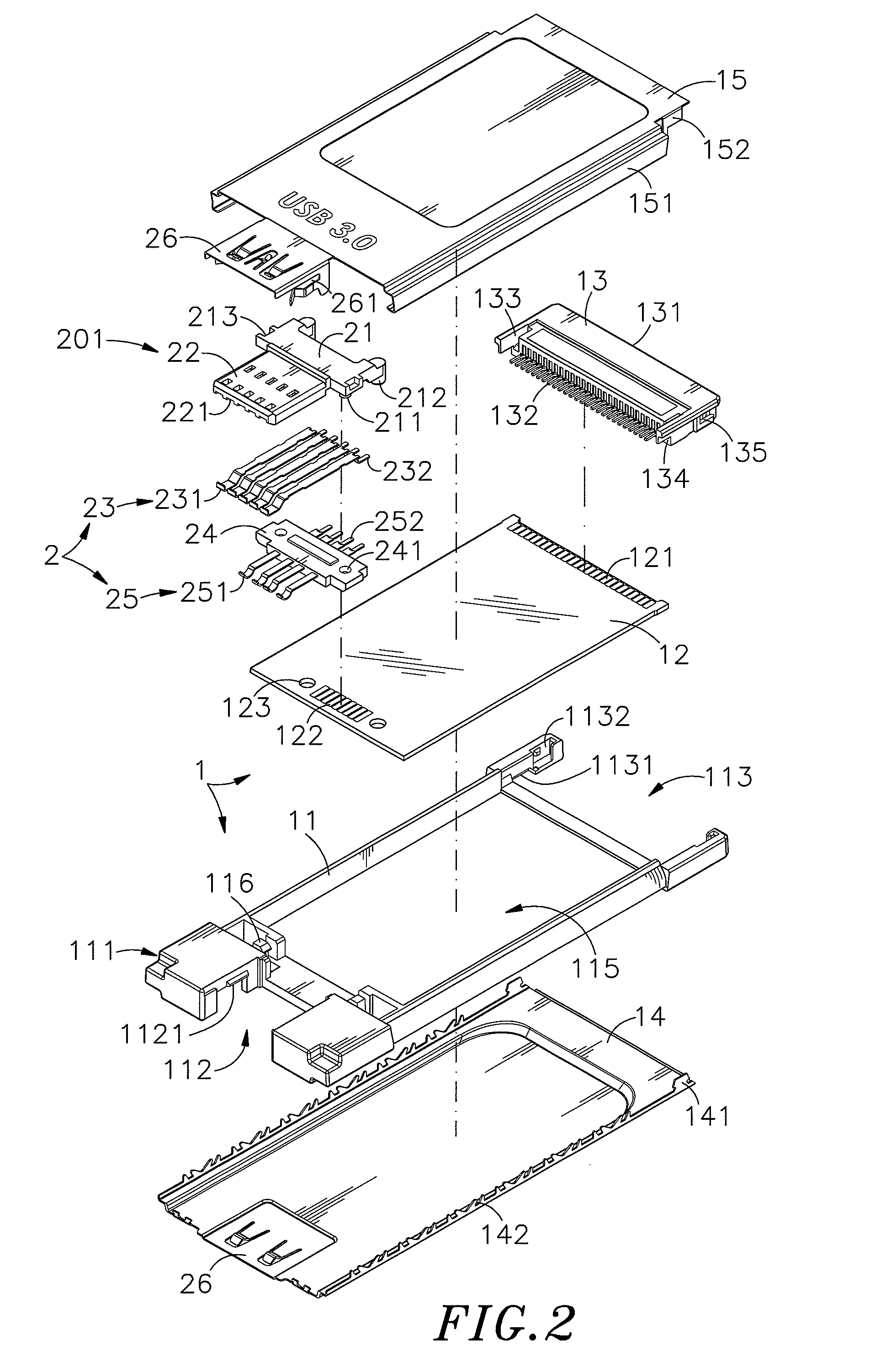
[0019]Referring to FIGS. 1˜4, an USB based ExpressCard device in accordance with a first embodiment of the present invention is shown comprising an ExpressCard 1 and a USB connector 2 installed in one side of the ExpressCard 1. The USB connector 2 according to this embodiment is a female type USB3.0 connector.

[0020]The ExpressCard 1 comprises an electrically insulative bracket 11, a circuit board 12, a terminal holder block 13, a bottom cover shell 14 and a top cover shell 15.

[0021]The electrically insulative bracket 11 comprises a front locating shell 111 located on one side, namely, the front side, an opening 112 vertically cut through the front locating shell 111, a retaining rib 1121 protruded from the front locating shell 111 at each of two opposite sides relative to the opening 112, a rear terminal holder block mounting structure 113 located on the other side, namely, the rear side and having retaining notch 1131 and a retaining groove 1132 disposed at each of two opposite lat...


PUM


Abstract

A USB based ExpressCard device having a dimension equal to a standard ExpressCard is disclosed to include an ExpressCard having a circuit board accommodated in an electrically insulative bracket and surrounded by a top cover shell and a bottom cover shell, and a USB3.0 connector mounted in an opening in a front locating shell of the electrically insulative bracket of the ExpressCard and having the rear bonding portions of first and second conducting terminals thereof respectively bonded to respective contacts at the circuit board by SMT (surface mounting technology).

Description

[0001]This application claims the priority benefit of Taiwan patent application number 098216746 filed on Sep. 10, 2009.BACKGROUND OF THE INVENTION[0002]1. Field of the Invention[0003]The present invention relates to ExpressCard technology and more particularly, to a USB based ExpressCard device, which incorporates a USB3.0 connector and an ExpressCard together, and employs SMT (surface mounting technology) to bond the rear bonding portions of the first and second conducting terminals of the USB3.0 connector to the circuit board of the ExpressCard, avoiding increasing the size.[0004]2. Description of the Related Art[0005]The ExpressCard standard specifies two factors, ExpressCard / 34 (34 mm wide) and ExpressCard / 54 (54 mm wide, in an L-shape). Using an ExpressCard in a notebook computer can expand the functions. Further, a USB based ExpressCard device is known, comprising a shell, a circuit board mounted in the shell, a terminal holder block located on the rear side of the circuit bo...

Claims


Application Information

Patent Timeline
Patent Type & Authority Applications(United States)
IPC IPC(8): G06F1/16
CPCY10S439/946H05K5/0282
Inventor LIN, HUN-YI
Owner D&C TECH
Learn More