Method and apparatus for determining the mis-alignment in images

Inactive Publication Date: 2011-03-10
SONY CORP
View PDF11 Cites 31 Cited by
  • Summary
  • Abstract
  • Description
  • Claims
  • Application Information

AI Technical Summary

Benefits of technology

[0015]This allows for mis-alignment between two images to be measured.
[0016]The image characteristic in the first or second image

Problems solved by technology

However, due to the complexity of the alignment process, these rigs take a long time to set up.
This is very undesirable, particularly in live television production where the sho

Method used


Image

  • Method and apparatus for determining the mis-alignment in images
  • Method and apparatus for determining the mis-alignment in images
  • Method and apparatus for determining the mis-alignment in images

Examples


Embodiment Construction

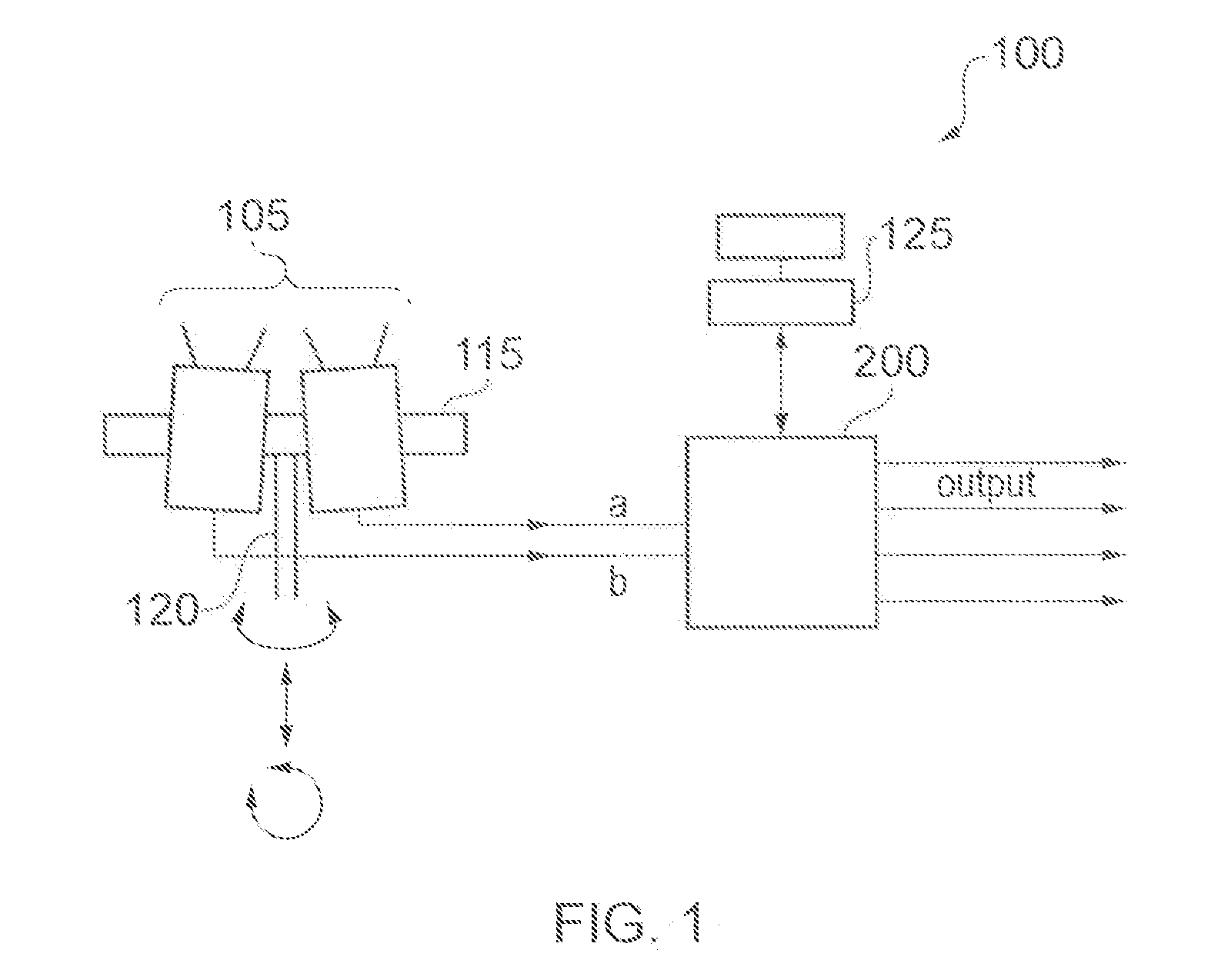
[0059]Referring to FIG. 1, a system 100 for capturing images of a scene for use in generating a 3D image is shown. The system 100 has a camera rig 115 upon which two cameras 105 are mounted. These cameras may be video cameras or still cameras. Although not shown in FIG. 1, the yaw of each camera 105 relative to each other can be changed. Specifically, whilst mounted on the rig 115, the pitch and roll of each camera 105 is usually fixed relative to one another. However, the yaw of each camera 105 can be adjusted independently of one another. This allows the cameras 105“toe-in” to be changed. Once locked in place (i.e. fixed to the rig 115), the yaw, pitch and roll of the rig 115 can be moved in unison. The yaw, pitch and roll of the rig 115 is moved by arm 120. The position of the rig 115 can be locked in place by twisting arm 120.

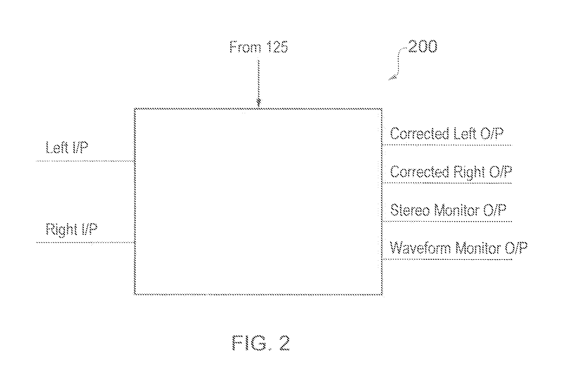
[0060]The output feed from each camera 105 is fed into a workstation 200 according to embodiments of the present invention. These outputs are labelled a an...


PUM


Abstract

A method of determining the amount of mis-alignment in one direction of an image of a scene, the image captured by a first camera is described. The method comprising the steps of:
    • defining a line between a first point in the image and a second point in the image, the line extending in the direction of mis-alignment;
    • defining a reference section in the scene to which the image is to be aligned, the reference section of the scene having a reference image characteristic;
    • identifying an image characteristic at different points along the line in the image; and
    • comparing the image characteristic at each point along the line with the reference image characteristic, and determining the amount of mis-alignment by determining the distance between the position of the reference image characteristic of the reference section captured in the image and the defined reference section in the scene.

Description

BACKGROUND OF THE INVENTION[0001]1. Field of the Invention[0002]The present invention relates to a method and apparatus for determining the mis-alignment in images.[0003]2. Description of the Prior Art[0004]In order to make 3 dimensional (3D) images it is necessary to take two shots of the same scene and displace one image slightly relative to the other image. This means that it is necessary to carefully align the images before the images are displaced. In order to achieve this alignment a special camera rig is normally used to capture the two shots. One such rig is produced by 3ality.[0005]However, due to the complexity of the alignment process, these rigs take a long time to set up. This is very undesirable, particularly in live television production where the shooting schedule is closely managed.[0006]Further, these rigs are very expensive. Typically, the cost of a 3D rig is so high that they are rented by program-makers rather than purchased.[0007]It is desirable therefore to pr...

Claims


Application Information

Patent Timeline
IPC IPC(8): G06K9/68
CPCG06T7/0028H04N13/0011G06T2207/30204G06T2207/10012G06T7/33H04N13/111
Inventor COOPER, RICHARD JARED
Owner SONY CORP
Why Eureka
Try Eureka