Centrifugal fan

a centrifugal fan and fan body technology, applied in the direction of machines/engines, stators, liquid fuel engines, etc., can solve the problems of brackets that vibrate with respect to the bottom wall of the housing, bolts that may easily disengage from the screw holes of the bottom wall, and electrical components operating at high speed generate excessive hea

Inactive Publication Date: 2011-03-10
HON HAI PRECISION IND CO LTD
View PDF4 Cites 31 Cited by
  • Summary
  • Abstract
  • Description
  • Claims
  • Application Information

AI Technical Summary

Problems solved by technology

Electronic components operating at high speed generate excessive heat which must be removed efficiently to ensure normal operation.
The impeller is liable to cause the bracket to vibrate with respect to the bottom wall of the housing.
This means the bolts may easily disengage from the screw holes of the bottom wall when the centrifugal fan has operated for a long time.

Method used


Image

  • Centrifugal fan
  • Centrifugal fan
  • Centrifugal fan

Examples


Embodiment Construction

[0012]Reference will now be made to the drawings to describe the present centrifugal fan in detail.

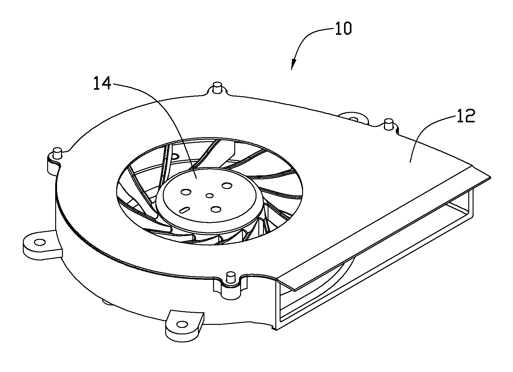
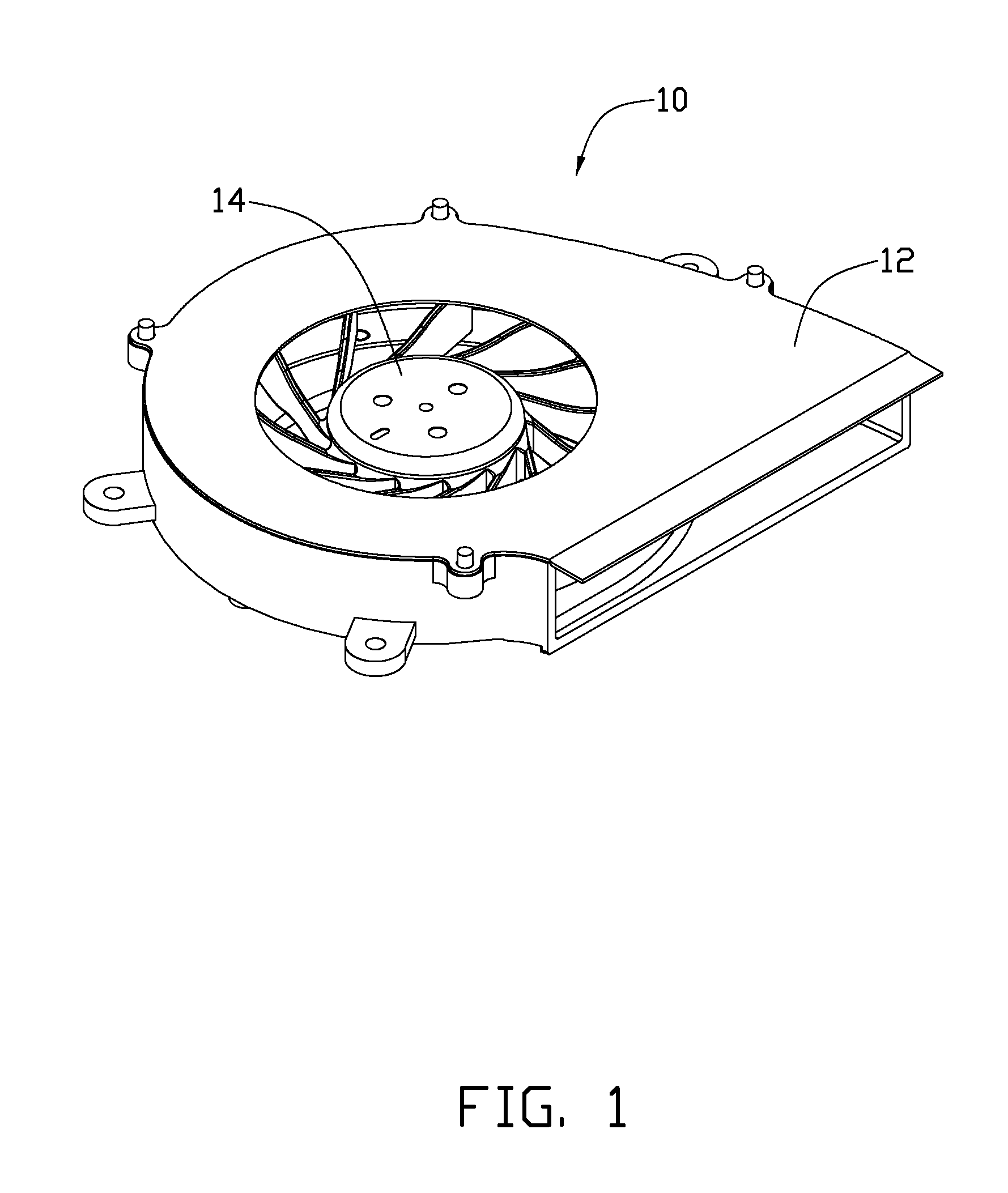
[0013]FIG. 1 illustrates a centrifugal fan 10 for dissipating heat generated by an electronic component (not shown). The centrifugal fan 10 includes a housing 12 and an impeller 14 received in the housing 12.

[0014]Referring also to FIGS. 2 and 3, the housing 12 includes a bottom frame 16, a bracket 18 and a top cover 19.

[0015]The bottom frame 16 includes a bottom wall 160, and a volute sidewall 162 extending upwardly and perpendicularly from an outer periphery of the bottom wall 160. A first circular air inlet 164 is defined in a central portion of the bottom wall 160. A substantially rectangular air outlet 166 is defined in one lateral side of the sidewall 162. The bottom wall 160 and the sidewall 162 cooperatively define a space 161 for receiving the impeller 14 therein. An annular step 163 is formed around the first air inlet 164. The step 163 has a bottom surface higher than a bott...


PUM


Abstract

A centrifugal fan includes an impeller and a housing receiving the impeller therein. The impeller includes a hub and blades extending radially from the hub. The housing includes a bottom wall, a sidewall extending upwardly from the bottom wall and a bracket for supporting the impeller thereon. The bottom wall defines an air inlet therein. A plurality of protruding posts extend downwardly from a bottom surface of the bottom wall around the air inlet. Each of the protruding posts defines a screw hole therein. The bracket is located in the air inlet. The bracket defines a plurality of through holes corresponding to the protruding posts respectively. The protruding posts of the bottom wall are respectively inserted into the through holes of the bracket. A plurality of bolts are respectively screwed into the screw holes of the protruding posts to connect the bracket and the bottom wall together.

Description

BACKGROUND[0001]1. Technical Field[0002]The disclosure relates to heat dissipation fans, and particularly to a centrifugal fan for dissipating heat generated by an electronic component.[0003]2. Description of Related Art[0004]Electronic components operating at high speed generate excessive heat which must be removed efficiently to ensure normal operation. Typically, a fan is used in combination with a heat dissipation device to produce an airflow in order to remove heat from the electronic components. Many portable electronic systems, such as a laptop computer or a notebook computer, are crammed with electronic components. There is little free space inside the computer. Accordingly, a centrifugal fan which requires only a small space for installation is generally used.[0005]The centrifugal fan includes a housing and an impeller received in the housing. The housing is usually made of plastic material. An air inlet is defined in a central portion of a bottom wall of the housing. A bra...

Claims


Application Information

Patent Timeline
Patent Type & Authority Applications(United States)
IPC IPC(8): F04D29/44
CPCF04D29/626F04D29/4226
Inventor CHEN, RUNG-AN
Owner HON HAI PRECISION IND CO LTD
Why Eureka
Try Eureka