
Wireless ultrasonic diagnostic apparatus and ultrasonic probe

a diagnostic apparatus and ultrasonic probe technology, applied in ultrasonic/sonic/infrasonic diagnostics, instruments, magnetic properties, etc., can solve the problems of ultrasonic observation device not receiving radio signals, communication failure between ultrasonic probe and ultrasonic observation devi

Inactive Publication Date: 2011-03-17
FUJIFILM CORP
View PDF14 Cites 15 Cited by
  • Summary
  • Abstract
  • Description
  • Claims
  • Application Information

AI Technical Summary

Benefits of technology

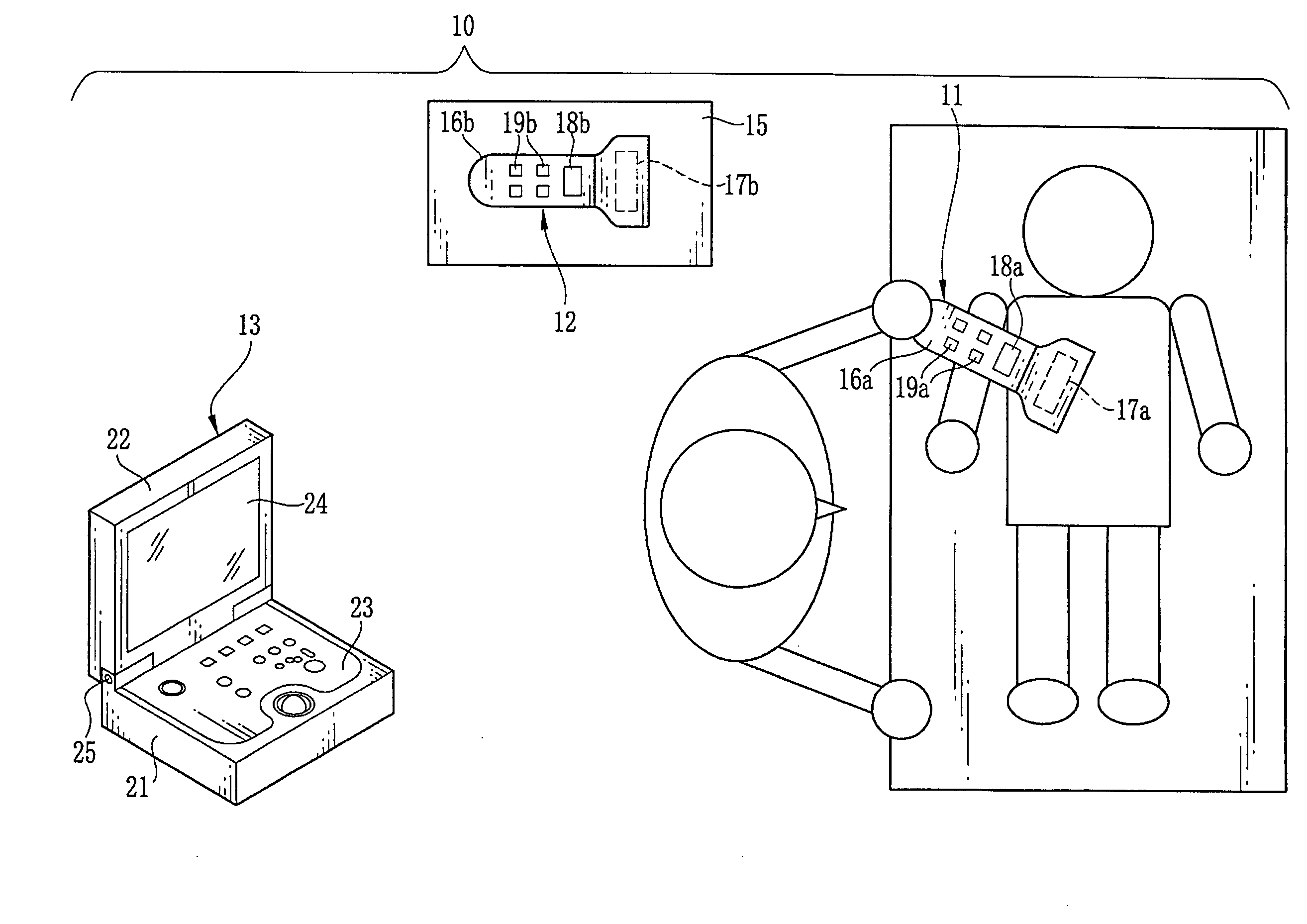
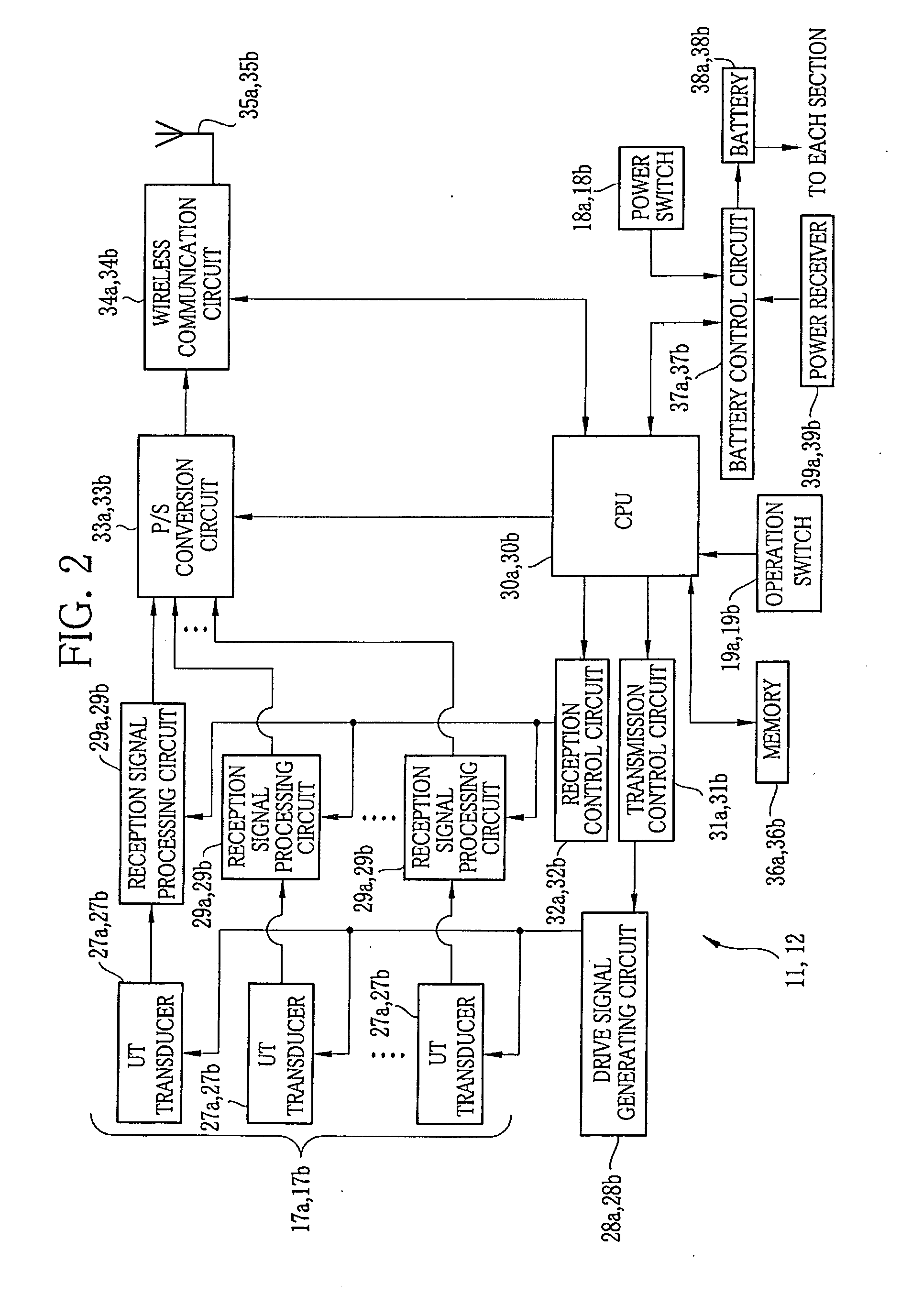
[0018]In the present invention, the ultrasonic probe not being used for the ultrasonic diagnosis is used to relay radio signals transmitted and received between the ultrasonic probe being used for the ultrasonic diagnosis and the ultrasonic observation device. Accordingly, even if an operator or an obstruction is located between the ultrasonic probe and the ultrasonic observation device, robust wireless communication network is constructed without being affected by the obstruction. As a result, good communication condition can be kept between the ultrasonic probe and the ultrasonic observation device.
[0023]Instead of inputting an operation to the ultrasonic probe being used for ultrasonic diagnosis, the operation can be input to the ultrasonic probe not being used for the diagnosis. As a result, the ultrasonic probe being used for the diagnosis is prevented from being moved due to the input operation during the diagnosis.
[0024]During the relaying of the radio signals, the ultrasonic probe displays that it is currently used for the relaying. As a result, the ultrasonic probe is prevented from being used for other purposes during the relaying of the radio signals.

Problems solved by technology

The wireless ultrasonic diagnostic apparatus, on the other hand, may cause communication failure between the ultrasonic probe and the ultrasonic observation device due to a position of an operator or a layout of an examination room.
As a result, the ultrasonic observation device fails to receive the radio signals.

Method used


Image

  • Wireless ultrasonic diagnostic apparatus and ultrasonic probe
  • Wireless ultrasonic diagnostic apparatus and ultrasonic probe
  • Wireless ultrasonic diagnostic apparatus and ultrasonic probe

Examples


first embodiment

[0117]In FIG. 10, an operation of the ultrasonic diagnostic apparatus 65 having the above configuration is described. In the following embodiments, descriptions already described in the first embodiment are omitted. The second ultrasonic probe 12 receives one block of the radio serial signals through the antenna 35b. The radio serial signals are modulated into the serial signals in the wireless communication circuit 34b, and then temporarily stored in the memory 36b.

[0118]The backup controller 68 copies the serial signals in the memory 36b to create the backup data 66. Thereafter, the serial signals in the memory 36b are demodulated into the radio serial signals in the wireless communication circuit 34b, and then transmitted to the ultrasonic observation device 13 through the antenna 35b.

[0119]When the transmission of the radio serial signals is started using the second ultrasonic probe 12, the communication status checker 69 checks the communication status between the second ultr...

second embodiment

[0125]In the above second embodiment, the backup data 66 is sequentially stored in the memory 36b. However, if the interruption time of the communication between the second ultrasonic probe 12 and the ultrasonic observation device 13 is long, an amount of the backup data 66 stored in the memory 36b increases while a remaining capacity of the memory 36b decreases. In this case, the second ultrasonic probe 12 and / or the ultrasonic observation device 13 may provide an alarm or warning, for example, an LED lamp or beep sound, to notify the operator the communication failure.

[0126]In the above second embodiment, the backup of the serial signals is performed in the second ultrasonic probe 12 as an example. Alternatively or in addition, the backup of the serial signals may be performed in the first ultrasonic probe 11. Information other than the serial signals may also be backed up. For example, the delay pattern information, the route request information 59 and / or the route information 58...

third embodiment

[0141]In the ultrasonic diagnostic apparatus 85, the CPU 40 of the ultrasonic observation device 13 functions as the routing controller 91 different from the third embodiment and as a route information selector 92. In the case where there are four transmission routes of the radio signals, the routing controller 91 generates the first to the fourth route information 93-(1) to 93-(4) corresponding to the four transmission routes. The route information selector 92 compares the first to the fourth route information 93-(1) to 93-(4), and selects the optimum transmission route.

[0142]Generation of the first route information 93-(1) is described with referring to FIGS. 16A to 16D. As shown in FIG. 16A, the route request information 89 generated by the routing controller 88a is modulated into radio signals and then broadcasted. The broadcast radio signals are received by the second ultrasonic probe 12.

[0143]Thereafter, the radio signals are demodulated into the route request information 89, ...


PUM


Abstract

A wireless ultrasonic diagnostic apparatus is composed of a first ultrasonic probe, a second ultrasonic probe, and an ultrasonic observation device each having wireless communication function. The first ultrasonic probe is used for ultrasonic diagnosis. The second ultrasonic probe, not being used for the ultrasonic diagnosis, is disposed in an area in which coverage of the first ultrasonic probe and coverage of the ultrasonic observation device overlap with each other. The second ultrasonic probe relays radio detection signals output from the first ultrasonic probe to the ultrasonic observation device.

Description

FIELD OF THE INVENTION[0001]The present invention relates to a wireless ultrasonic diagnostic apparatus for transmitting and receiving radio signals between an ultrasonic probe and an ultrasonic observation device, and an ultrasonic probe included in this wireless ultrasonic diagnostic apparatus.BACKGROUND OF THE INVENTION[0002]Medical diagnoses using an ultrasonic diagnostic apparatus are prevalent. The ultrasonic diagnostic apparatus is composed of an ultrasonic probe and an ultrasonic observation device. At a tip of the ultrasonic probe, ultrasonic transducers (hereinafter referred to as UTs) are arranged. The UTs emit ultrasonic waves to a human body, and receive reflected waves from an object of interest in the human body. Thereby, detection signals are output. The detection signals are electrically processed in the ultrasonic observation device. Thus, an ultrasonic image is obtained.[0003]A wireless ultrasonic diagnostic apparatus is known as one of the examples of the ultraso...

Claims


Application Information

Patent Timeline
IPC IPC(8): G01N29/00
CPCA61B8/00A61B8/4455A61B8/4472G01N29/2481A61B2562/08G01N29/0654A61B8/467A61B8/461
Inventor NISHINO, TOMOHIRO
Owner FUJIFILM CORP
Learn More