Method and Apparatus for Cementing a Liner in a Borehole Using a Tubular Member Having an Obstruction

a tubular member and cementing technology, which is applied in the direction of drilling casings, borehole/well accessories, pipes, etc., can solve the problems of inability to use the wiper dart of the drill pipe member, the procedure just discussed is not suitable for use with the tubular member, and the inability to cement the liner in the well

Inactive Publication Date: 2011-03-17
BAKER HUGHES INC +1
View PDF5 Cites 9 Cited by
  • Summary
  • Abstract
  • Description
  • Claims
  • Application Information

AI Technical Summary

Benefits of technology

[0012]An open hole is drilled with coiled tubing that has an electric line. At the conclusion of drilling the drilling bottom hole assembly is removed and a liner running tool is connected between the coiled tubing and the liner. The electric line remains in the coiled tubing but spacers can be added to keep the lower end of the electric line away from the running tool. A wiper plug has a passage therethrough and a movable stinger that can hold open a pair of flapper valves. The liner is released from the running tool and cement is delivered through the stinger with a bit of excess that is above the running tool. The lifting of the stinger with the coiled tubing closes the flappers and allows circulation out of excess cement. Setting down on the coiled tubing allows a seal to re-engage in the deployment sleeve, allowing pressure to be placed against the wiper plug, such that it can be launched to displace the remaining cement within the liner into the annulus around the liner.
[0049]a) positioning a liner in the open borehole, the liner extending from a toe end of the liner near a toe end of the open borehole to a deployment sleeve positioned on a heel end of the liner and located in the production tubing, the deployment sleeve being adapted to sealingly connect to a liner running tool, the liner running tool including an extension and having a passageway through the liner running tool and the extension, the heel end of the liner having a liner wiper plug with an opening therein extending through the liner wiper plug so that fluids may be conveyed therethrough, the extension of the liner running tool being in fluid communication with and extending through the opening so that fluids conveyed by the tubular member may be conveyed through the passageway and the opening through the liner wiper plug, the liner wiper plug having a cover biased to cover the opening and restrict flow of fluids through the opening when the extension is withdrawn from the opening and a releasable retaining apparatus adapted to releasably retain the liner wiper plug in a selected position in the liner;

Problems solved by technology

Unfortunately this procedure is not suitable for use with a tubular member containing an obstruction, since the obstruction inhibits or otherwise prohibits travel of the tubular member wiper dart.
It will be immediately apparent that the procedure just discussed is not effective to cement liners in wells using a tubular member, including a wire, since the wire makes it impossible to pass the tubular member wiper dart through the tubular member.
Similarly drillpipe, which is also a suitable tubular member, is not effective when the drillpipe includes an obstruction which makes it impossible to use a drillpipe member wiper dart.
This has been a necessary operation and can be quite expensive and time consuming.

Method used


Image

  • Method and Apparatus for Cementing a Liner in a Borehole Using a Tubular Member Having an Obstruction
  • Method and Apparatus for Cementing a Liner in a Borehole Using a Tubular Member Having an Obstruction
  • Method and Apparatus for Cementing a Liner in a Borehole Using a Tubular Member Having an Obstruction

Examples


Embodiment Construction

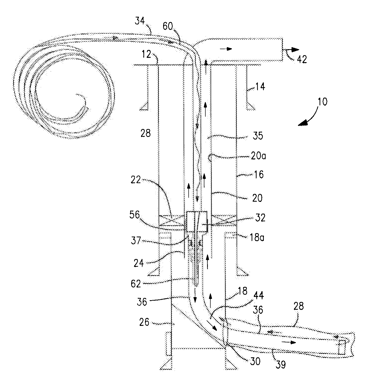
[0067]In the discussion of the Figures which follows, the same numbers will be used throughout to refer to the same or similar components. Various components are shown schematically which are otherwise considered to be well known to those skilled in the art for simplicity.

[0068]The method and apparatus of the present invention are useful with coiled tubing or other tubular members used for cementing liners in position in boreholes, such as drillpipe. For illustration, the method and apparatus are shown and discussed by reference to a coiled tubing system working through production tubing. The use of the method and apparatus is essentially the same with or without the production tubing.

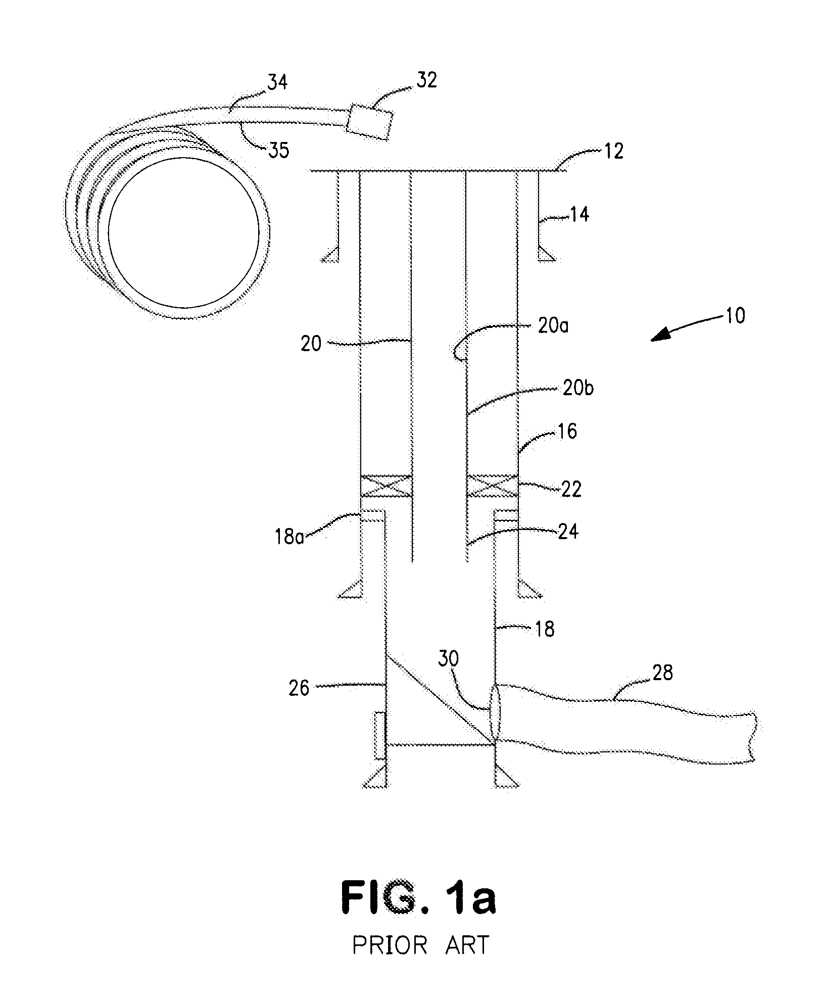
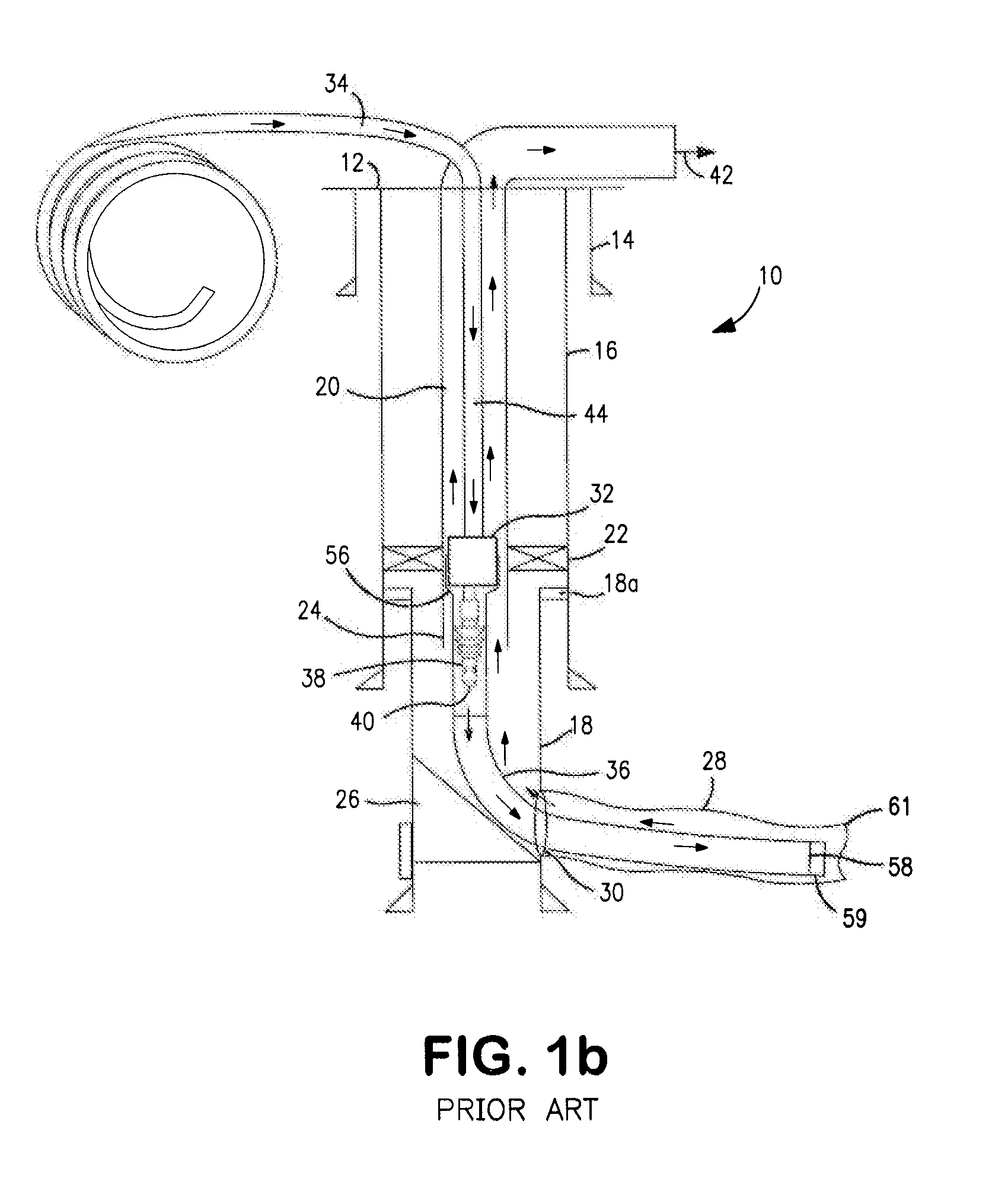
[0069]In FIGS. 1a-1e a prior art method for cementing a liner in a borehole is shown. The first step, shown as FIG. 1a, is the completion of a cased wellbore 10 which extends from an earth surface 12 to a subterranean formation and includes an outer casing 14, a second casing 16 and a third casing 18 s...


PUM


Abstract

An open hole is drilled with coiled tubing that has an electric line. At the conclusion of drilling the drilling bottom hole assembly is removed and a liner running tool is connected between the coiled tubing and the liner. The electric line remains in the coiled tubing but spacers can be added to keep the lower end of the electric line away from the running tool. A wiper plug has a passage therethrough and a movable stinger that can hold open a pair of flapper valves. The liner is released from the running tool and cement is delivered through the stinger with a bit of excess that is above the running tool. The lifting of the stinger with the coiled tubing closes the flappers and allows circulation out of excess cement. Setting down on the coiled tubing allows a seal to re-engage in the deployment sleeve, allowing pressure to be placed against the wiper plug, such that it can be launched to displace the remaining cement within the liner into the annulus around the liner.

Description

CROSS REFERENCE TO RELATED APPLICATION[0001]This application is a continuation of U.S. patent application Ser. No. 12 / 640,942, filed Dec. 17, 2009, which claims the benefit of U.S. Provisional Application Ser. No. 61 / 203,567, filed Dec. 23, 2008, the teachings of which are incorporated herein by reference in their entirety and U.S. patent application Ser. No. 12 / 637,105, filed Dec. 14, 2009, which claims the benefit of U.S. Provisional Application Ser. No. 61 / 122,914, Dec. 16, 2008.FIELD OF THE INVENTION[0002]The present invention relates to a method and apparatus for cementing a liner in place in an open borehole using a tubular member having an obstruction in the tubular member where cement is passed through the tubular member into the liner and through the liner into an annular space surrounding the liner to position the liner in the open borehole. More particularly the invention relates to liner cementing of a well drilled with electric line coiled tubing using the same coiled t...

Claims


Application Information

Patent Timeline
Patent Type & Authority Applications(United States)
IPC IPC(8): E21B33/12E21B7/00
CPCE21B33/14E21B19/22
Inventor JOHNSON, MARKHARRIS, ROBERT
Owner BAKER HUGHES INC
Why Eureka
Try Eureka