
Transformable Robotic Platform and Methods for Overcoming Obstacles

a robotic platform and transformable technology, applied in the field of robotics, can solve the problems of complex control system, limited operability of the robotic platform, and addition of another level of complexity to the task

Inactive Publication Date: 2011-03-17
DEFENSE VISION
View PDF4 Cites 23 Cited by
  • Summary
  • Abstract
  • Description
  • Claims
  • Application Information

AI Technical Summary

Benefits of technology

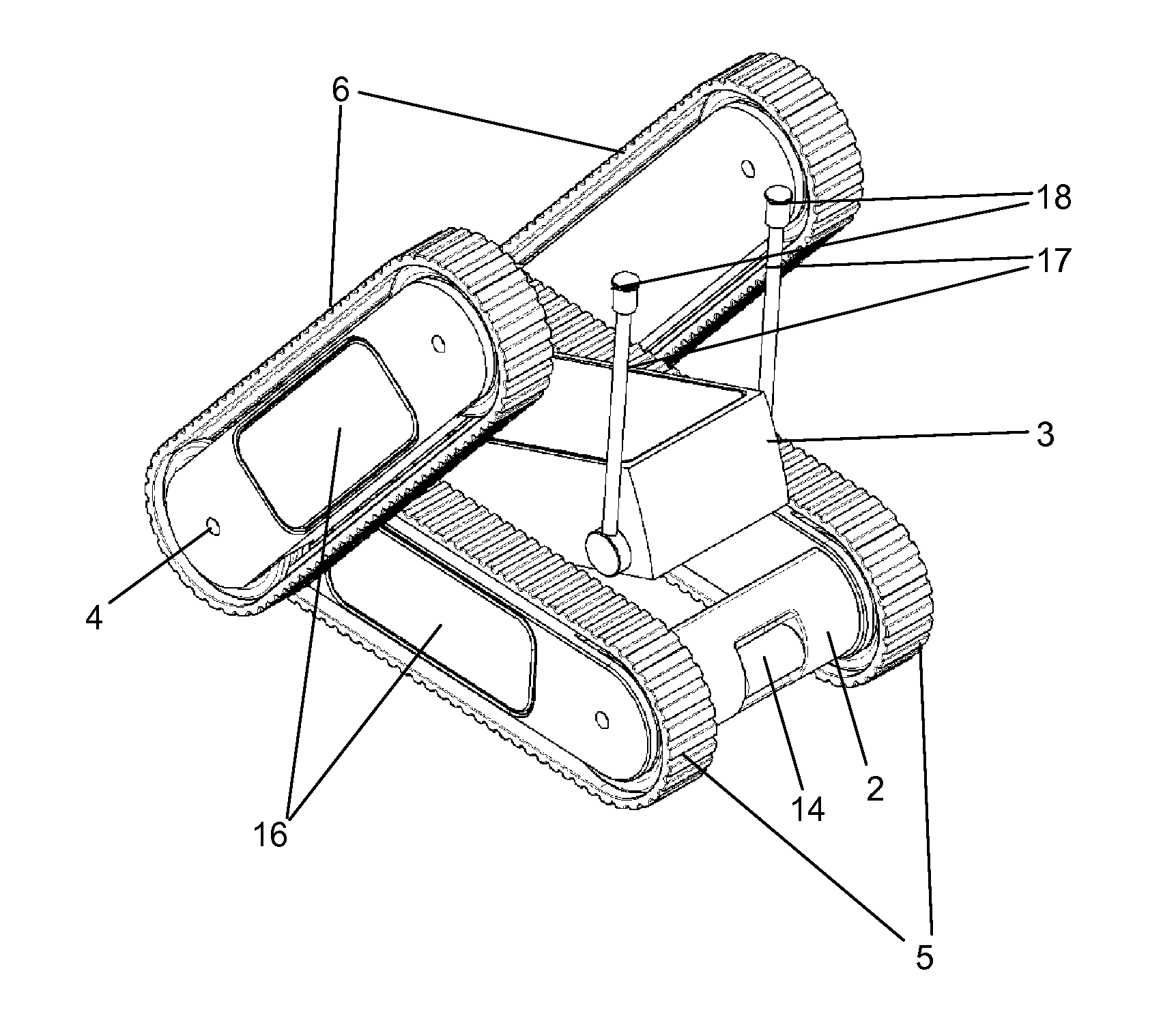
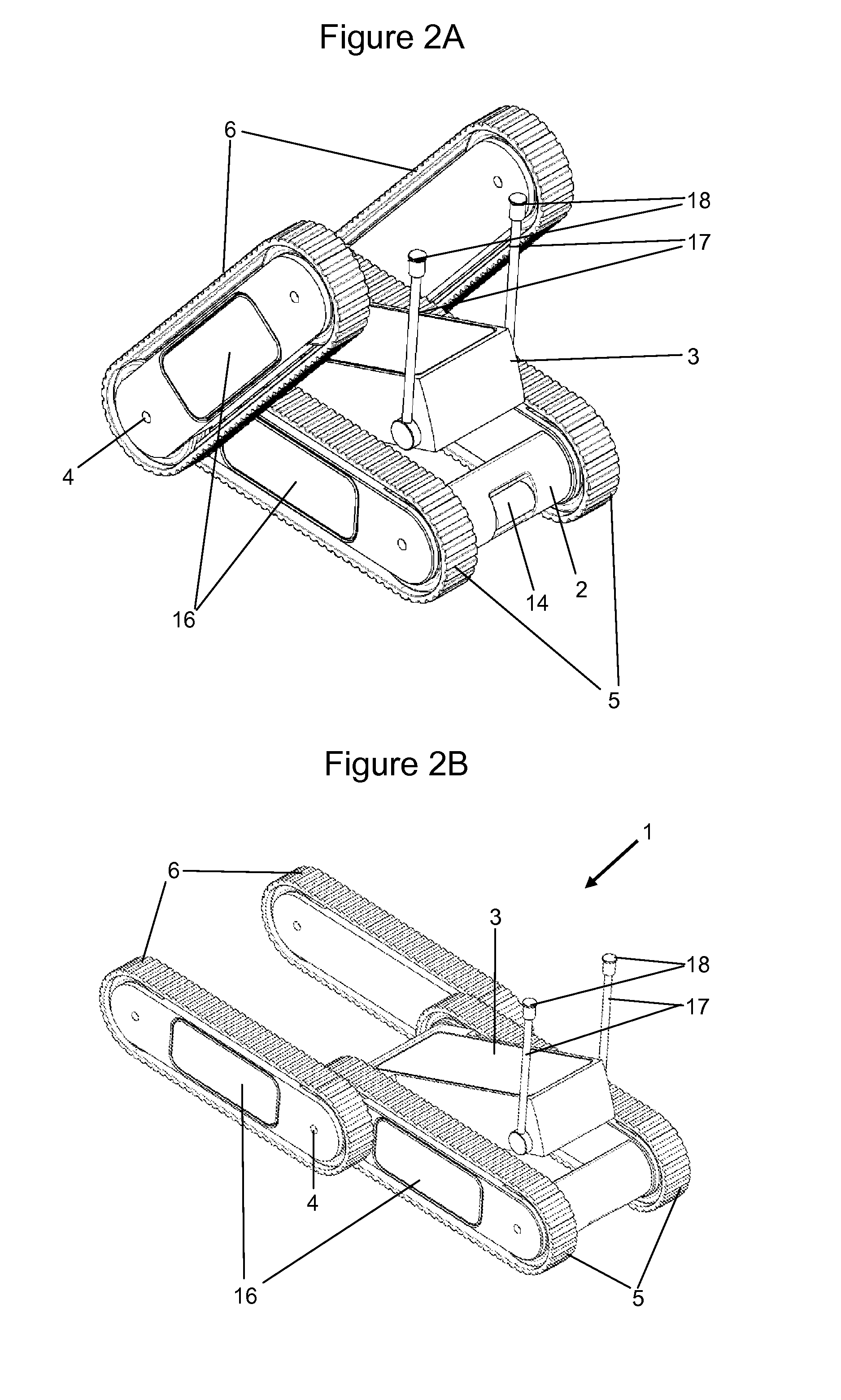
[0052]A method of overcoming obstacles may further include pivoting the second pair of tracks around the axis in order to move the center of gravity of the platform forward and provide more traction of the first pair of tracks on the obstacle subsequent to driving the first pair of tracks onto the obstacle.

Problems solved by technology

1. Flipping Mechanisms focus on flipping the entire robotic platform over when it inadvertently lands in a nonpreferred orientation. The robotic platform is usually designed to be fully operational only in a preferred orientation. Nevertheless, the robotic platform has limited operability including in nonpreferred orientation. Particularly, a flipping mechanism is operative in the nonpreferred orientation for flipping the robotic platform over to its preferred orientation. Subsequent to flipping, the robot resumes full operability.
2. Sensors Deflection provides double sided operation capability without the need to flip the entire robotic platform over. Full, or nearly full, operability is available in multiple orientations by tilting the robotic platform's sensors relative to the side on which the platform operates, via electro-mechanic mechanisms.
3. Firmware / electronics-based solutions may be used on a symmetric platform which is designed to operate in multiple orientations without engaging dedicated mechanical mechanisms, neither to flip the entire platform, nor to tilt its sensors. Firmware is used to adjust the information displayed to the operator according to the orientation of the platform and to control the signals which are provided from the operator.
One major challenge in the field of robotics is mobility, in other words, the ability to drive a robotic platform from one point to another.
Another level of complexity is added to this task when the control over the platform is to be maintained during changing environmental conditions such as darkness, harsh weather, etc.
This results in a complex control system, and a high level of training and expertise is required in order to simultaneously maneuver the platform and operate operational devices.
The difficulty is compounded under adverse conditions and combat pressures for military robots.
In addition, multiple dedicated control units become quite bulky and may not fit operational needs (for example when a robot is to be controlled by a soldier on the battle field).
Controlling the robot is especially complex when synchronization is to be maintained while the robotic platform is in motion.
Nevertheless, both copending applications (Gal '884 and Gal '955) are limited in that they can not significantly raise their operational devices (for example for operation while hiding behind a tall obstacle) and they can not traverse many extreme obstacles.
The main drawbacks of such a Flipping Mechanism and of a Flipping Maneuver associated therewith from an operational point of view are; (i) the need to perform the Flipping Maneuver when the platform lands on its back side delays the platform's operation; (ii) during the Flipping Maneuver, the elongated arm that extends out of the secured main frame is vulnerable to damage; (iii) the need to perform the Flipping Maneuver may jeopardize the operation of the platform when it lands near obstacles that might prevent performing the Flipping Maneuver.
Won does not also address the problem of synchronization.
Furthermore, Won does not address the limitations of symmetrical bilateral operation which requires directing the sensors horizontally instead of tilting the sensors towards the desired region of interest, which is usually elevated relatively to the low profile platform.
Hence, the platform may basically roll down over obstacles.
However, the platform of Gal '585 lacks the ability to actively climb obstacles such as stairs.

Method used


Image

  • Transformable Robotic Platform and Methods for Overcoming Obstacles
  • Transformable Robotic Platform and Methods for Overcoming Obstacles
  • Transformable Robotic Platform and Methods for Overcoming Obstacles

Examples


embodiment 101

[0142]FIG. 7 schematically shows a perspective view of an embodiment 101 of a bilateral robotic platform having an articulated operational assembly 103, a main frame 102, a axis 104, first pair 105 of tracks, second pair 106 of tracks, antennas 117, and sensors and detectors 118.

[0143]In second preferred embodiment, an operational assembly 103 is pivotally connected to a main frame 102 by a revolute joint via a universal joint 182.

embodiment 2

[0144]In embodiment 2, the robotic platform can switch into “Exploring Mode” according to which the operational assembly 103 is tilted and traversed according to commands sent by a remote operator in order to investigate regions of interest of the remote operator's choice. The articulation of operational assembly 103 enables the investigation of regions of interest all around the robotic platform's surroundings while eliminating the need to rotate the entire robotic platform.

[0145]In embodiment 2, universal joint 182 includes a slip ring mechanism to supply power and communication connections between operational assembly 103 and main frame 102 while providing continuous 360 degree tilting of the operational assembly 103 in either direction without tangling wires. Alternatively, the operational assembly 103 and the main frame 102 may include separable power supplying units and communicate over wireless channels in order to eliminate the need to incorporate a slip ring mechanism into ...


PUM


Abstract

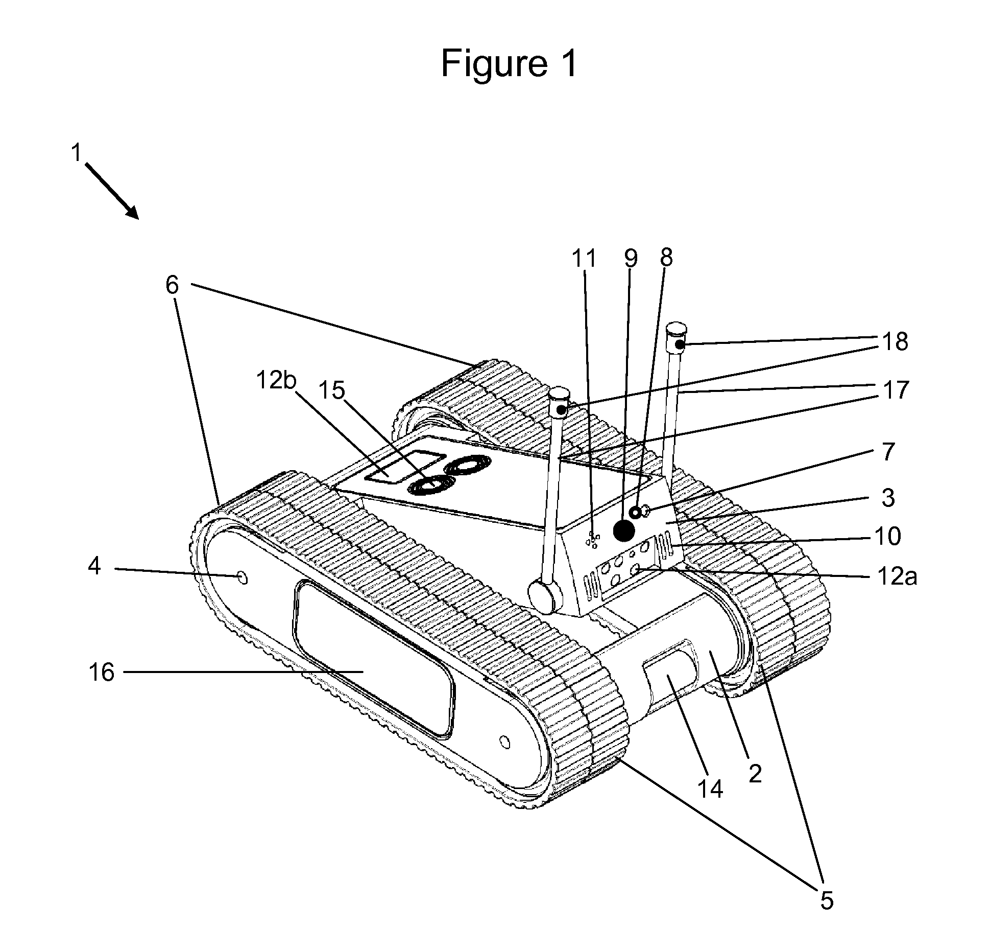
A transformable robotic platform includes a main frame and a tiltable central assembly and two pairs of parallel tracks. A first pair of tracks is fixed to the main frame while a second pair of tracks is pivotable with respect to the main frame. The central assembly incorporates imaging means, designation means and operational means in a synchronized manner, thus simplifying the maneuvering of the robotic platform and the operation of its operational means by a remote operator. Tilting the central assembly as well as the second pair of tracks shifts the center of gravity of the robotic platform rearward decreasing downward gravitational force on the front end of the platform facilitating climbing over obstacles. Tilting the central assembly also provides double-sided operation and about face operation of the robotic platform without the need to perform maneuvers which flip over the entire robotic platform. The pivoting of second pair of tracks enables transformation of the robotic platform into a quasi pyramid position in order to provide a superior position for information gathering and for operation.

Description

[0001]This patent application claims the benefit of U.S. Provisional Patent Application No. 61 / 241,972 filed 14 Sep. 2009.FIELD AND BACKGROUND OF THE INVENTION[0002]The present invention is related to the field of robotics; more specifically the invention is related to the field of electro-mechanics for remotely controlling a transformable robotic platform with extended operational and maneuvering capabilities.[0003]The art of robotics has increasingly developed throughout the years and many solutions have been offered by the art in order to overcome the various challenges inherent in the field. The solutions offered by the art are usually customized to the requirements for which a robotic platform is designed.[0004]Bilateral operation capability in the field of robotics means the ability of a robotic platform to operate on two different sides with respect to the architecture of the robotic platform. This capability is sometimes referred to in the art as double-sided operation, dual...

Claims


Application Information

Patent Timeline
IPC IPC(8): B62D55/00
CPCB62D55/075B62D55/065
Inventor GAL, EHUD
Owner DEFENSE VISION
Learn More