
Reality based training target trap

Inactive Publication Date: 2011-03-17
AWARENESS PROTECTIVE CONSULTANTS
View PDF24 Cites 16 Cited by
  • Summary
  • Abstract
  • Description
  • Claims
  • Application Information

AI Technical Summary

Benefits of technology

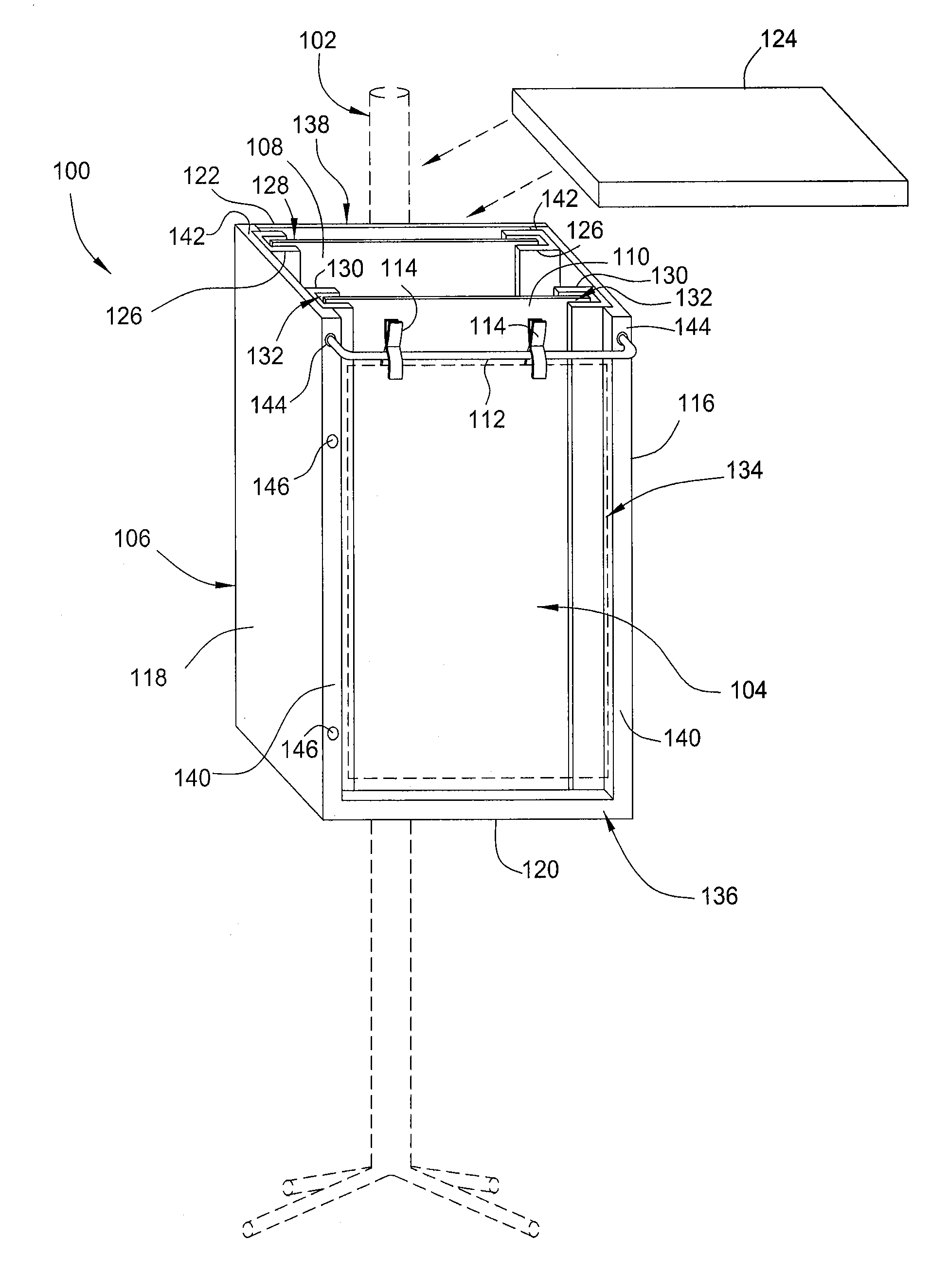
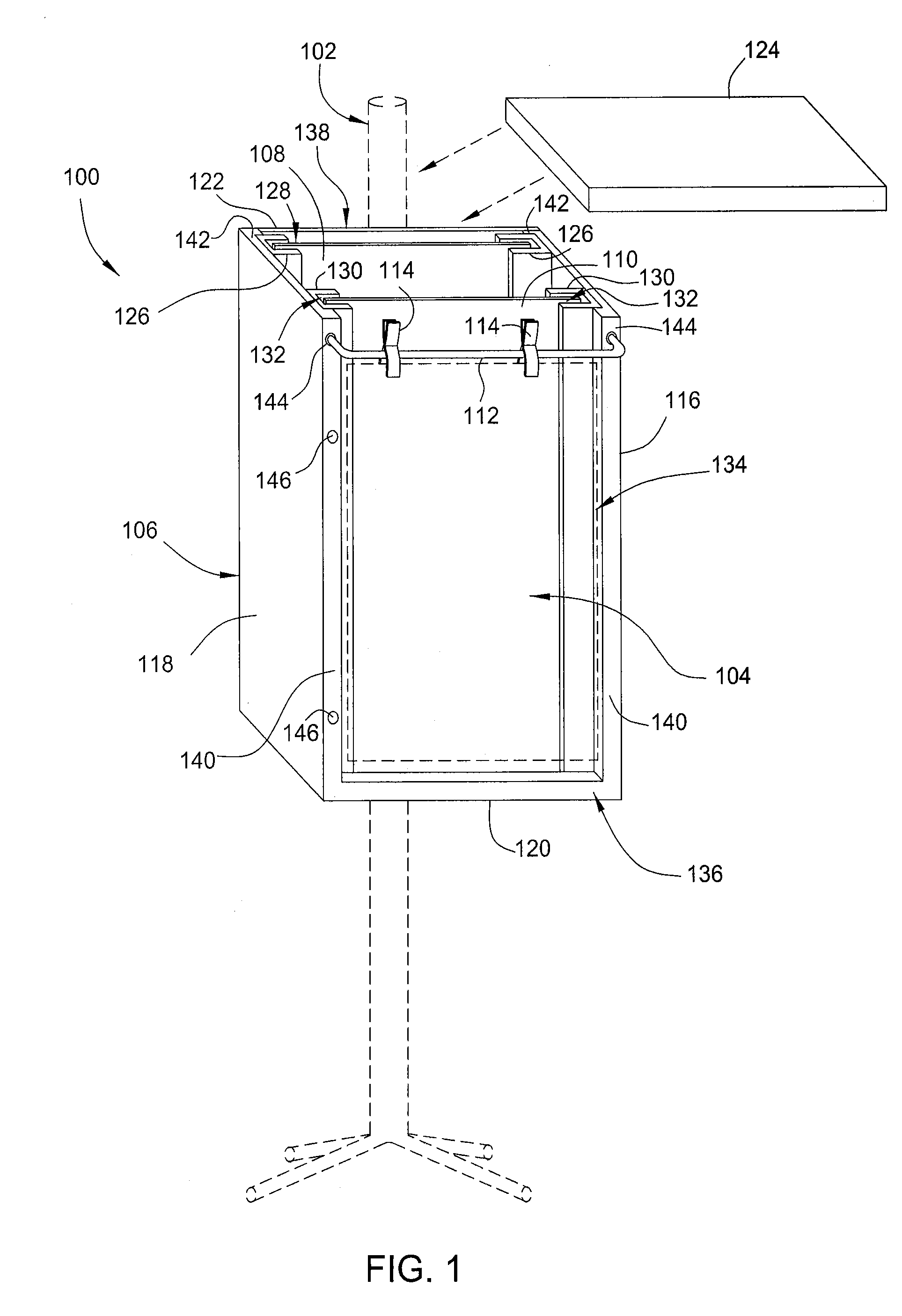
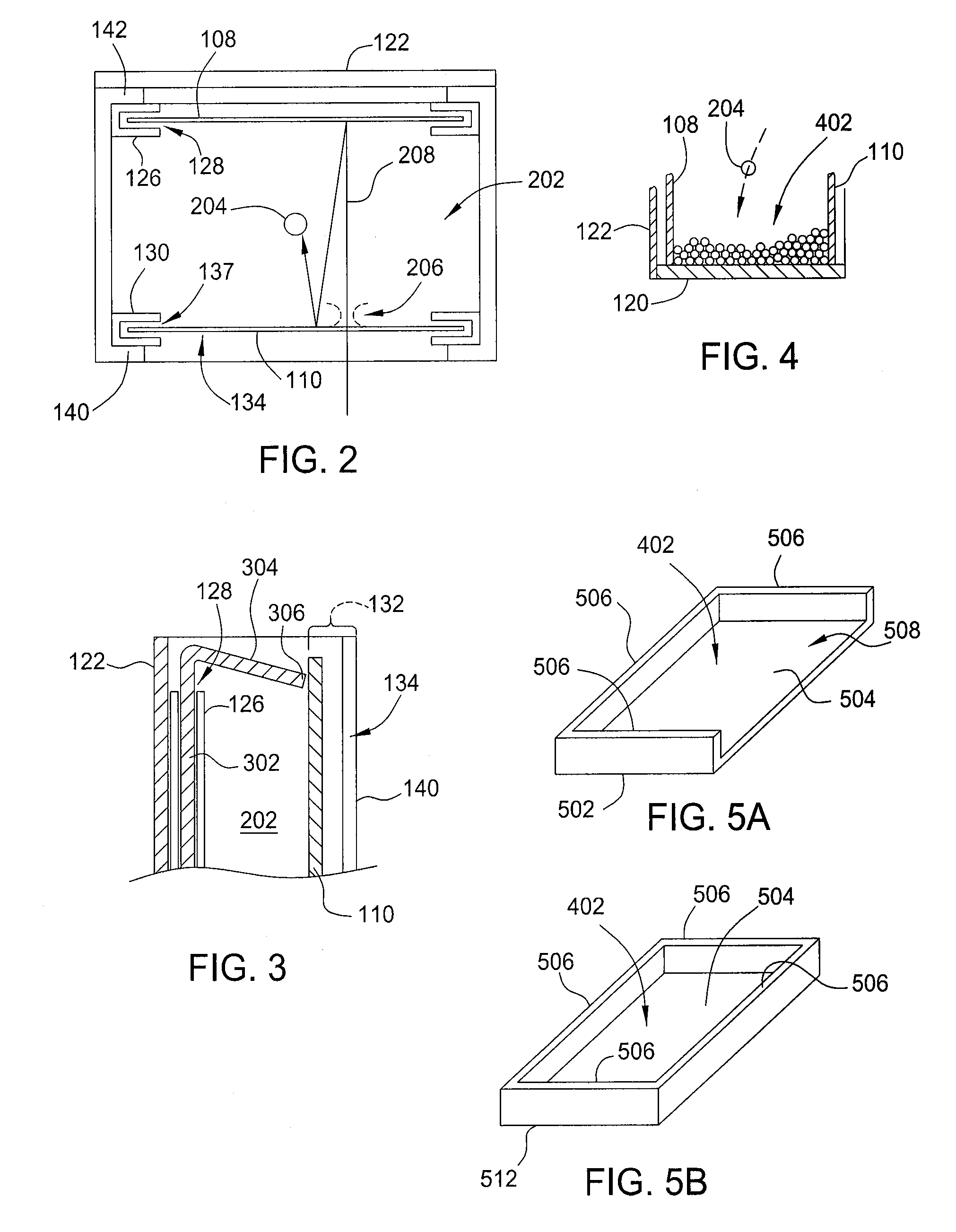
[0007]A target trap suitable for use in reality-based training methods is provided. The target trap may advantageously capture pellets and marking rounds for improved clean-up and cost-saving re-use of ammunition. The target trap has a replaceable strike panel and face panel, and allows for paper or cardboard targets to be hung easily on its front surface by using clamps or tacks or other type of clips. The target trap is also light-weight and weather resistant, and may be easy rotated for use in both portrait and landscape orientations, which enable the trap to be utilized in a broad range of reality-based training exercises.
[0009]In another embodiment is a target trap is provided that includes a frame assembly having removable face and strike panels. The frame assembly includes a bottom wall and back wall coupling a first sidewall to an opposing second sidewall. An opening is defined between the first and second sidewalls of the frame assembly. The strike panel disposed within a back slot defined between the first and second sidewalls opposite the opening of the frame assembly. The back slot loosely retains the strike panel in a manner that allows lateral movement of the strike panel in a direction perpendicular to a plane of the opening. The face panel is disposed within the frame assembly between the opening and the strike panel, and is space apart from strike panel. The back wall includes at least one mounting feature located on a vertical centerline of the back wall and at least one mounting feature centered on a horizontal centerline of the back wall to allow the trap to be supported in either a portrait or landscape orientation.

Problems solved by technology

Placement of targets is limited to places where a target can be supported, as well as what is behind the target which could be damaged as the pellet or marking round passes through.
However, the cost of new pellets and marking rounds over time becomes a limiting factor in the volume of shooting and training that occurs.
Additionally, the cleanup of training areas after a training exercise has been completed is consuming and tedious work.
Conventional target traps are difficult to clean or are intended as a single use product, which although suitable for recreational use, do not lend themselves to high volume use.

Method used


Image

  • Reality based training target trap
  • Reality based training target trap
  • Reality based training target trap

Examples


Embodiment Construction

[0023]FIG. 1 depicts one embodiment of a target trap 100 mounted on a stand 102 (shown in phantom) that supports a target 104 (also shown in phantom). Generally, the target trap 100 is suitable for capturing and retaining pellets fired at the target 104. In the embodiment shown, the target trap 100 includes a frame assembly 106, a strike panel 108, a face panel 110, and an optional target support 112 that is utilized with clips 114 to secure the target 104 to the frame assembly 106. While the below description refers to “pellets”, it is understood that the target trap 100 is suitable for capturing and retaining many projectiles, including but not limited to, airsoft pellets, plastic pellets, lead pellets, BBs, marking rounds, paintballs, and the like.

[0024]The frame assembly 106 houses the strike panel 108 and the face panel 110 and collects pellets entering the trap 100. As shown in FIG. 1, the frame assembly 106 has a front 136 and a back 138, and includes a bottom wall 120, and s...


PUM


Abstract

A target trap having improved portability is provided. The target trap is suitable for use in reality-based training methods and may advantageously capture pellets and marking rounds for improved clean-up and cost-saving re-use of ammunition. The target trap has a replaceable strike panel and face panel and allows for paper or cardboard targets of various dimensions to be hung on its front surface by using clamps or tacks or other type of clips.

Description

CROSS-REFERENCE TO RELATED APPLICATION[0001]This application claims benefit to U.S. Provisional Application Ser. No. 61 / 276,602, filed Sep. 14, 2009 by Jose L. Medina and Arthur G. Randolph, which is incorporated by reference in its entirety.BACKGROUND OF THE INVENTION[0002]1. Field of the Invention[0003]The present invention generally relates to target traps for use with reality-based methods of target training, as well as shooting skill development through the use of simulation or marking round firearms.[0004]2. Description of the Related Art[0005]Generally, shooting skill development and law enforcement / counter terrorism tactics have advanced through the use of paintball, simulation and marking round weaponry. The use of targets in such activities is a critical component in such activities. Traditional targets are usually a paper product which pellets penetrate easily. The targets are supported by a trap, which captures the round to prevent damaging the surrounding area. Placemen...

Claims


Application Information

Patent Timeline
IPC IPC(8): F41J13/00
CPCF41J13/00
Inventor MEDINA, JOSERANDOLPH, ARTHUR G.
Owner AWARENESS PROTECTIVE CONSULTANTS
Learn More