Check patentability & draft patents in minutes with Patsnap Eureka AI!

Touch sensing apparatus with parasitic capacitance prevention structure

Inactive Publication Date: 2011-03-17
MELFAS
View PDF10 Cites 44 Cited by
  • Summary
  • Abstract
  • Description
  • Claims
  • Application Information

AI Technical Summary

Benefits of technology

[0010]The touch sensing apparatus of FIG. 4 includes the sensing electrodes 110 formed on a rear surface of a window 100. The window 100 may be formed of a dielectric, such as a tempered glass or acrylic, and a front surface of the window 100 may be exposed to an electronic device, to accommodate a touch of a user and to protect the sensing electrodes 110 and a display apparatus against an external environment.
[0031]FIG. 11 is an enlarged perspective diagram stereoscopically illustrating the configuration of FIG. 10. While the above-described shielding electrode 130 is not shown in FIG. 11, a configuration including a shielding electrode 130 configured as shown in FIG. 4 or 8, and a unit gain buffer 140 configured as shown in FIG. 4 or 8 to transfer voltages of the sensing electrodes 110, 1101, 1102, and 1103 to the shielding electrode 130 may also be added to the present embodiment. Specifically, the plurality of sensing electrodes 110, 1101, 1102, and 1103 arranged in a same layer may be connected to each other through the buffer 140 and thus, it is possible to prevent an occurrence of a parasitic capacitance. Additionally, it is possible to shield against noise transferred from a display module by separately arranging a shielding electrode 130 in a different layer from the sensing electrodes 110, 1101, 1102, and 1103.

Problems solved by technology

The noise signal may have influence on a performance of a touch screen, for example, may cause the touch screen to incorrectly recognize a touch of a user, or to obtain inaccurate touch position information.
However, actually, there are many cases where it is impossible to ensure a sufficient air gap 16 to block the noise signal due to a limitation in design based on a slim design of an electronic device.
The parasitic capacitance may greatly reduce a touch sensitivity in a capacitive-type touch screen, in particular.

Method used


Image

  • Touch sensing apparatus with parasitic capacitance prevention structure
  • Touch sensing apparatus with parasitic capacitance prevention structure
  • Touch sensing apparatus with parasitic capacitance prevention structure

Examples


Embodiment Construction

Technical Goals

[0008]Hereinafter, a touch sensing apparatus and a noise signal shielding apparatus according to the present invention will be described with reference to the accompanying drawings. In the following description, like or corresponding elements are denoted by like reference numerals, and overlapping descriptions will be omitted.

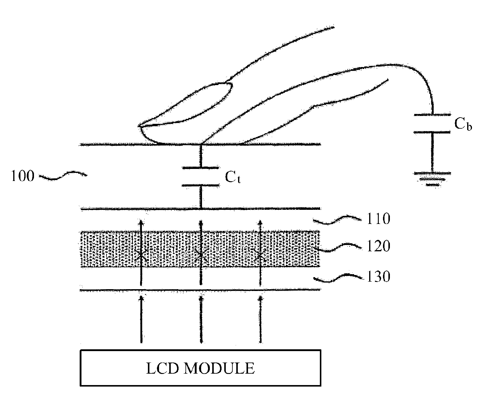
[0009]FIG. 4 illustrates a panel section structure and a functional configuration of a touch sensing apparatus according to an embodiment of the present invention. For convenience of description, an adhesive layer used to deposit sensing electrodes 110 and shielding electrodes 130 is not shown in FIG. 4.

[0010]The touch sensing apparatus of FIG. 4 includes the sensing electrodes 110 formed on a rear surface of a window 100. The window 100 may be formed of a dielectric, such as a tempered glass or acrylic, and a front surface of the window 100 may be exposed to an electronic device, to accommodate a touch of a user and to protect the sensing electr...


PUM


Abstract

The present invention relates to a touch sensing apparatus. The touch sensing apparatus of the present invention includes a first sensing electrode arranged on a rear surface of a window to sense the touch of a user on the window covering a display screen, a second sensing electrode superimposed onto the first sensing electrode with an insulating layer interposed therebetween, and a buffer for transmitting voltage of the first sensing electrode side to the second sensing electrode side. The touch sensing apparatus of the present invention is capable of effectively cutting off noise signals generated from a display module and keeping touch sensitivity at a high level.

Description

TECHNICAL FIELD[0001]The present invention relates to a touch sensing apparatus, and more particularly, to a touch sensing apparatus with a noise signal shielding structure and a parasitic capacitance prevention structure.BACKGROUND ART[0002]A touch sensing apparatus may be used as an input apparatus to sense a touch of a user applied to a specific position. Generally, the touch sensing apparatus may be configured to sense a touch based on a change in electrical characteristics caused by the touch of the user.[0003]FIG. 1 illustrates an example of a plane structure of a conventional touch sensing panel. The touch sensing panel of FIG. 1 includes a window 10 to accommodate a touch input, and sensing electrodes 15 that are arranged in regular intervals on a rear surface of the window 10. Each of the sensing electrodes 15 of FIG. 1 may be connected to one of M signal lines 11, and one of N signal lines 12. Here, the M signal lines 11 and the N signal lines 12 may be respectively used t...

Claims


Application Information

Patent Timeline
IPC IPC(8): G06F3/044G06F3/041
CPCG06F3/0418G06F3/044G06F2203/04107H02S20/00Y02E10/47F24J2/541F24J2002/5465F24J2002/5486Y02E10/50F24J2/5264G06F3/0446G06F3/0443
Inventor MIN, DONGJIN
Owner MELFAS
Features
  • R&D
  • Intellectual Property
  • Life Sciences
  • Materials
  • Tech Scout
  • Unparalleled Data Quality
  • Higher Quality Content
  • 60% Fewer Hallucinations
Learn More