Fixing device and image forming apparatus employing the fixing device

a fixing device and fixing device technology, applied in the direction of electrographic process apparatus, instruments, optics, etc., can solve the problems of insufficient abrasion resistance of the sliding surface between the ceramic heater and the fixing belt made of heat-resistant film, unsteady travel of the fixing belt, and wear of the sliding surfa

Active Publication Date: 2011-03-17
RICOH KK
View PDF9 Cites 122 Cited by
  • Summary
  • Abstract
  • Description
  • Claims
  • Application Information

AI Technical Summary

Benefits of technology

As described above, the fixing device according to any of the above-described exemplary embodiments includes the fixing member, the heat conductive member, and lubricant lying between the fixing member and the heat conductive member. With the fixing member stopped, the fixing device heats the heat conductive member using the heating member and, after the heating of the heat conductive member, rotates the fixing member. Such a configuration allows the fixing member to rotate after the viscosity of lubricant is reduced. Accordingly, the friction resistance of the sliding portion between the fixing member and the heat conductive member can be reduced, allowing stable operation of the fixing member, a reduced driving torque of the rotary drive unit that drives the fixing member, and a reduced load of the rotary drive unit. Thus, damage of the rotary drive unit can be prevented, allowing extension of the product life of the fixing device.
Further, the image forming apparatus including the fixing device according to any one of the above-described exemplary embodiments performs excellent and stable fixing processing to form a high quality image and achieves an increased product life.
According to the pressing-belt-type fixing device described above, pressure of the pressing pad elastically deforms the surface of the heat fixing roller and extends a contact area of the heat fixing roller and the recording medium to enhance heat conduction efficiency, reduce energy consumption, and achieve downsizing.

Problems solved by technology

For example, the abrasion resistance of a sliding surface between the ceramic heater and the fixing belt made of heat-resistant film may be insufficient.
When the fixing belt is driven for an extended period of time, the sliding surface is worn out.
Accordingly, traveling of the fixing belt may become unsteady and / or the driving torque of the fixing device may increase.
Consequently, the recording medium may slip on the fixing belt, causing displacement of a resultant image.
Alternatively, increased stress may be applied to a driving gear, causing damage to the gear.
The temperature of the fixing belt is at its lowest when the fixing belt in rotation returns to an entrance of the fixing nip, causing faulty fixing particularly at high-speed rotation.
However, in the above-described pressing-belt-type fixing device, a large heat capacity of the fixing roller may increase the time required for raising the temperature of the fixing roller, thereby extending the warm-up time.

Method used


Image

  • Fixing device and image forming apparatus employing the fixing device
  • Fixing device and image forming apparatus employing the fixing device
  • Fixing device and image forming apparatus employing the fixing device

Examples


Embodiment Construction

In describing embodiments illustrated in the drawings, specific terminology is employed for the sake of clarity. However, the disclosure of this patent specification is not intended to be limited to the specific terminology so selected and it is to be understood that each specific element includes all technical equivalents that operate in a similar manner and achieve similar results.

Although the exemplary embodiments are described with technical limitations with reference to the attached drawings, such description is not intended to limit the scope of the invention and all of the components or elements described in the exemplary embodiments of this disclosure are not necessarily indispensable to the present invention.

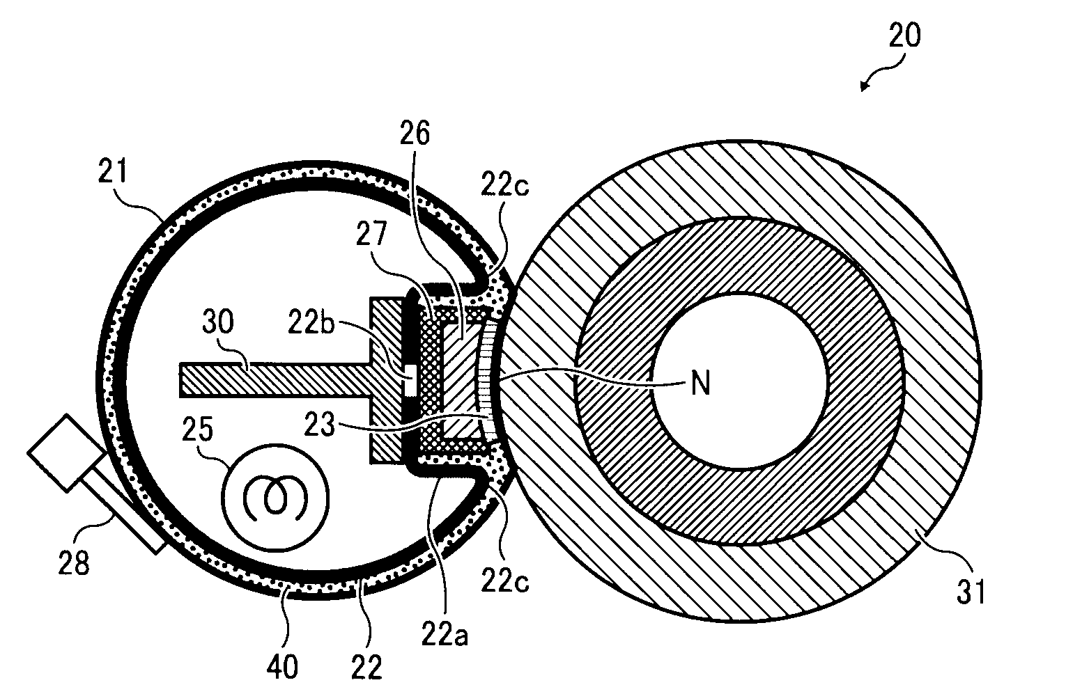
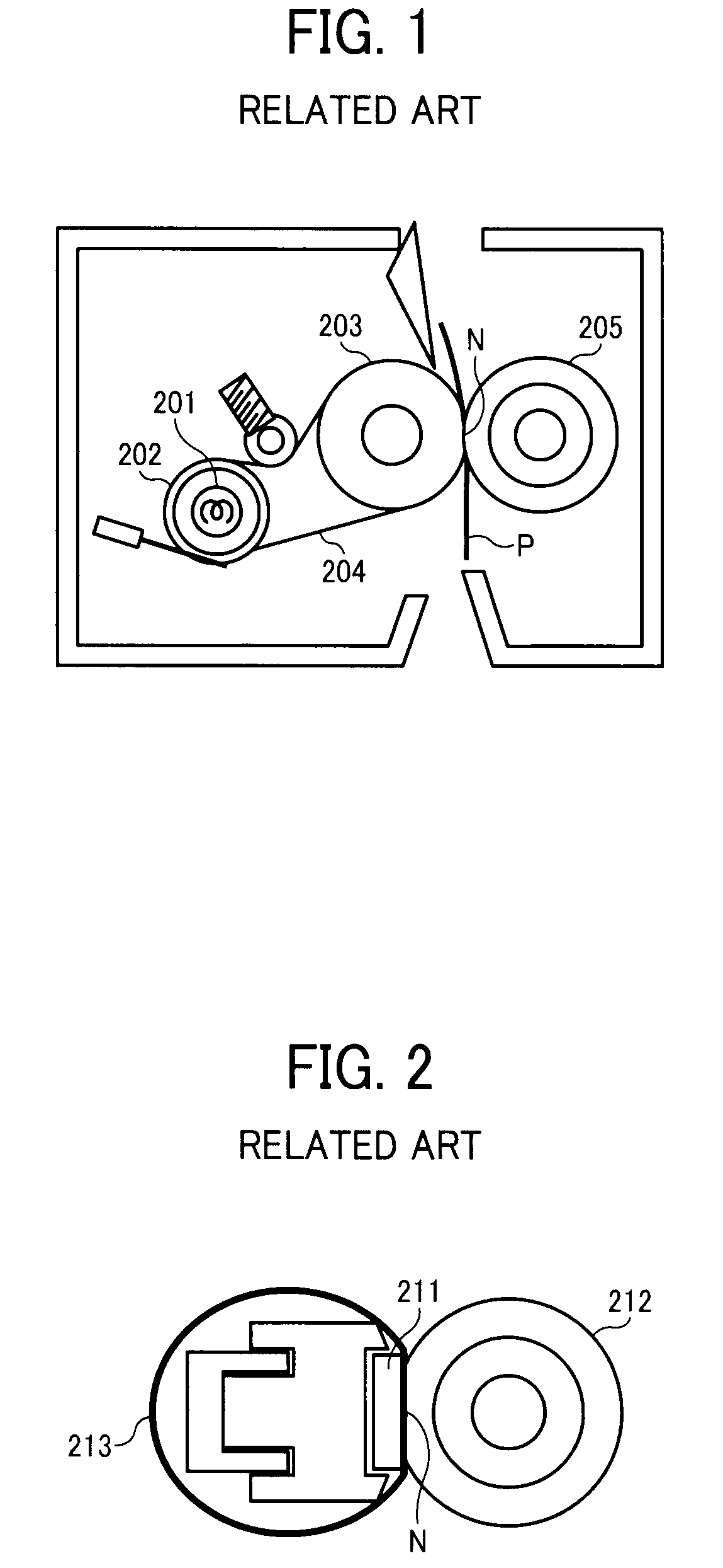
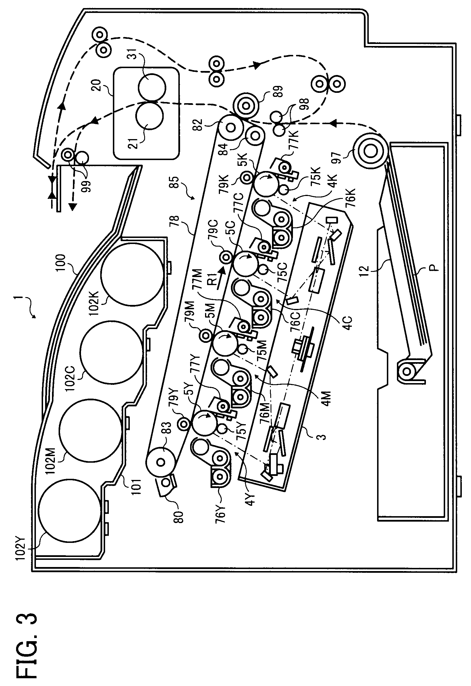
It is to be noted that, in the description below, reference characters Y, M, C, and K attached to the end of each reference numeral indicate only that components indicated thereby are used for forming yellow, magenta, cyan, and black images, respectively, and hereinafte...


PUM


Abstract

A fixing device for fixing an image on a recording medium includes an endless flexible fixing member formed into a loop, a heat conductive member disposed within the loop formed by the fixing member, a heater disposed near the heat conductive member to heat the heat conductive member, a pressing member pressing the fixing member against the heat conductive member to form a fixing nip, a temperature sensor detecting a temperature of the fixing member, and a lubricant disposed between the fixing member and the heat conductive member. The heater heats the heat conductive member to heat the lubricant with the fixing member stopped. The fixing member rotates after heating of the heat conductive member by the heater.

Description

BACKGROUND OF THE DISCLOSURE1. Field of the DisclosureExemplary embodiments of the present disclosure relate to a fixing device and an image forming apparatus including the fixing device, and more specifically, to a fixing device that applies heat and pressure to a recording medium at a nip between a fixing belt and a pressing member to fix an image on the recording medium and an image forming apparatus including the fixing device.2. Description of the BackgroundAs one type of image forming apparatus, electrophotographic image forming apparatuses are widely known. In an image formation process executed by an electrophotographic image forming apparatus, for example, a charger uniformly charges a surface of an image carrier (e.g., photoconductive drum); an optical writing unit emits a light beam onto the charged surface of the image carrier to form an electrostatic latent image on the image carrier according to image data; a development device supplies toner to the electrostatic laten...

Claims


Application Information

Patent Timeline
Patent Type & Authority Applications(United States)
IPC IPC(8): G03G15/20
CPCG03G15/2042G03G2215/2035G03G15/2053G03G15/205
Inventor YAMASHINA, RYOTASHINSHI, AKIRAHASEGAWA, KENICHIYOSHINAGA, HIROSHIISHIGAYA, YASUNORI
Owner RICOH KK
Why Eureka
Try Eureka