Axial turbine and method for discharging a flow from an axial turbine

a technology of axial turbine and axial turbine, which is applied in the direction of rotors, liquid fuel engines, machines/engines, etc., can solve the problems of large circumferential distortion of steam flow, uncircumferentially uniform steam operating conditions, and worsening the overall efficiency of steam turbine, so as to reduce mixing losses and pressure drops at the diffuser, and increase efficiency

Active Publication Date: 2011-03-17
GENERAL ELECTRIC TECH GMBH
View PDF6 Cites 2 Cited by
  • Summary
  • Abstract
  • Description
  • Claims
  • Application Information

AI Technical Summary

Benefits of technology

[0018]Another aspect includes an axial turbine and a method by which the mixing losses (due to the aforementioned non-uniformities) and pressure drops of the steam flow are reduced and the overall efficiency of the steam turbine is increased.

Problems solved by technology

Nevertheless, as the expansion stages of the turbine are axial symmetric, whereas the collector of the exhaust diffuser is neither axial symmetric, nor extends in the same direction as the expansion stages, when passing through the exhaust diffuser the steam flow undergoes large circumferential distortions.
This causes the operating conditions of the steam in the last expansion stage (in particular in the circumferential direction) to be influenced, such that in the last expansion stage the operating conditions of the steam are not circumferentially uniform.
Moreover, flow circumferential distortions cause non-uniform mixing losses within the steam flow and differing pressure drops that can worsen the overall efficiency of the steam turbine.

Method used


Image

  • Axial turbine and method for discharging a flow from an axial turbine
  • Axial turbine and method for discharging a flow from an axial turbine
  • Axial turbine and method for discharging a flow from an axial turbine

Examples


Embodiment Construction

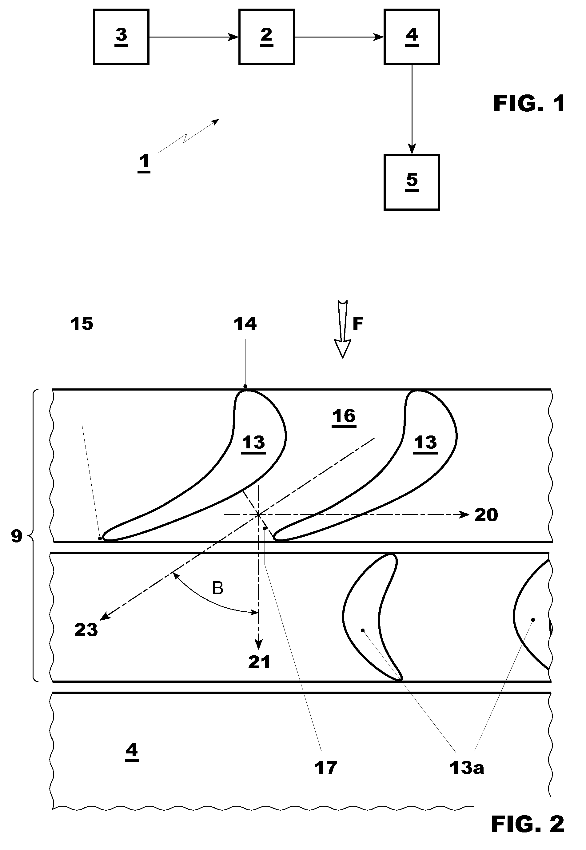
[0026]With reference to the figures (in particular FIG. 1), these schematically show an axial turbine overall indicated by the reference number 1.

[0027]The turbine 1 is a steam turbine and includes a plurality of expansion stages 2 where the high pressure and high temperature steam flow generated by a steam generator 3 is expanded to extract mechanical power.

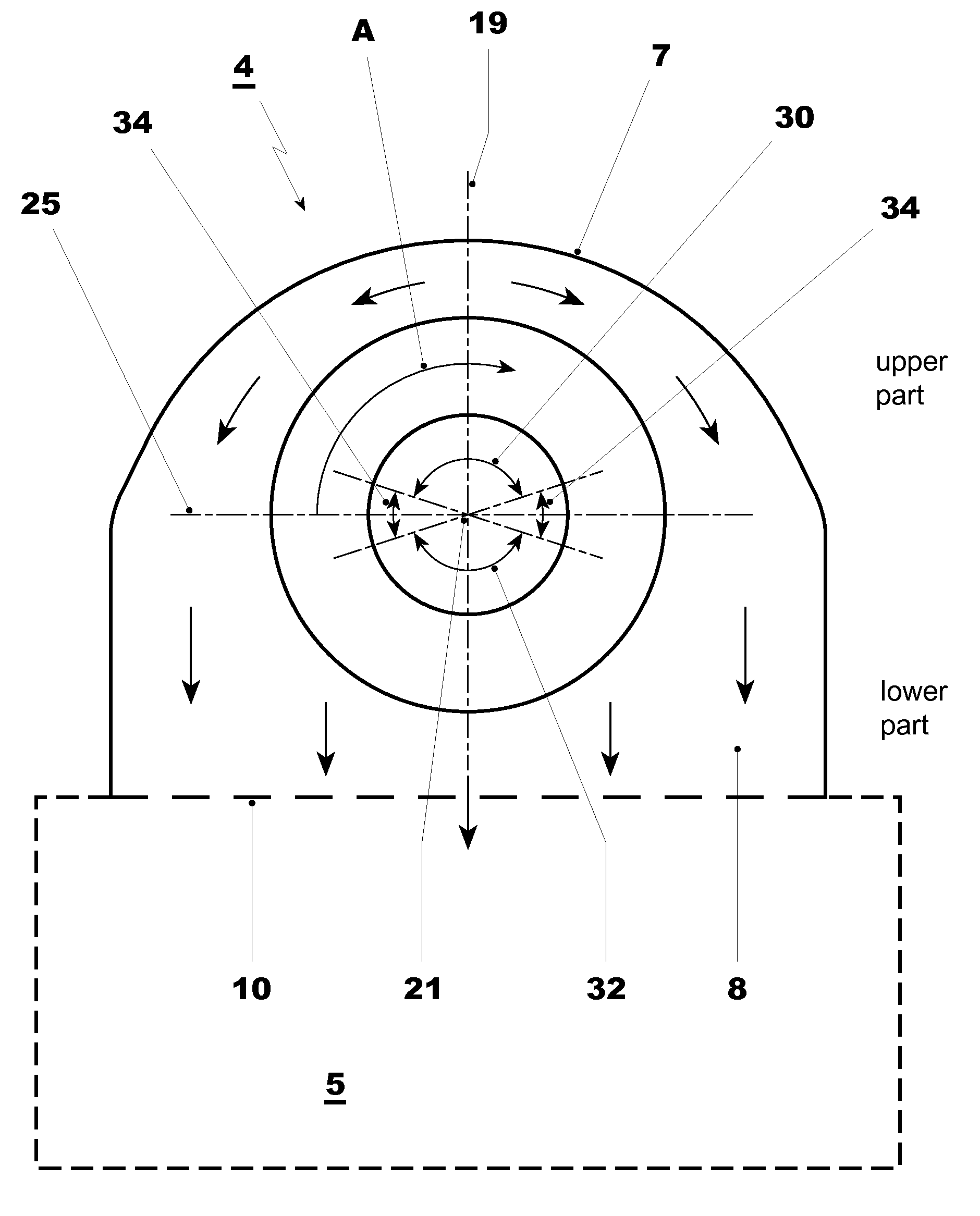
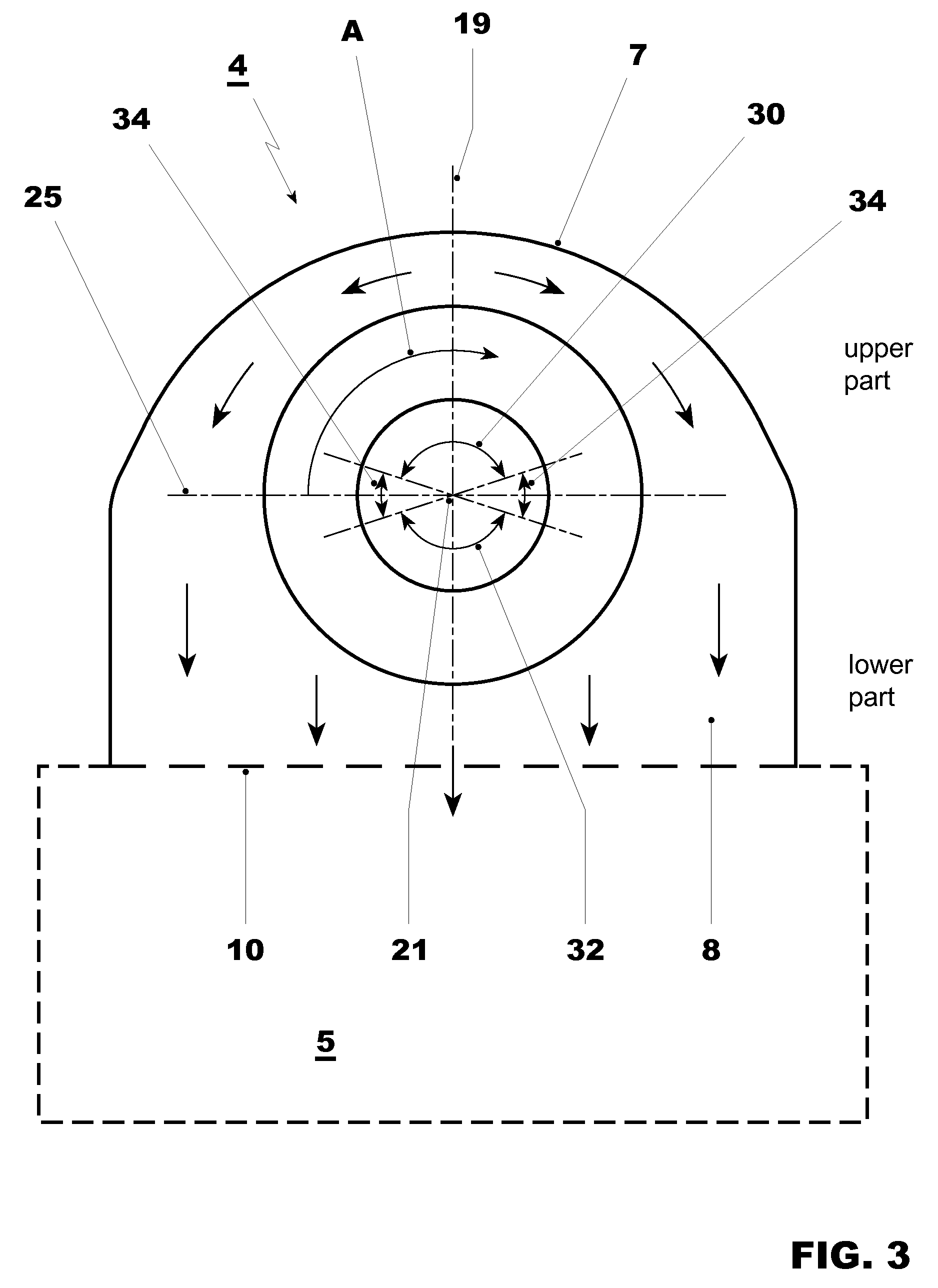
[0028]Downstream of the expansion stages 2 the steam turbine 1 includes an exhaust diffuser 4 that collects the steam flow passing through the expansion stages 2 and discharges it to the outside (into a condenser 5) along a direction different from that of the turbine axis.

[0029]FIG. 3 shows the turbine axis 21 of the turbine along which the steam flow propagates in the expansion stages 2, and the axis 19 along which the steam flow is diverted in the exhaust diffuser 4 to be discharged into the condenser 5.

[0030]Each expansion stage is defined by stator blades and rotor blades.

[0031]The stator blades are fixed to a blade carrier...


PUM


Abstract

An axial turbine (1) has a plurality of expansion stages (2) each defined by stator blades (13) and rotor blades. The expansion stages (2) are followed by an exhaust diffuser (4) for collecting the flow passing through the expansion stages (2) and discharging it to the outside. The expansion stages (2) and / or the diffuser (4) have at least a non-axial symmetric portion. The stator blades (13) define different openings (17) along the circumference of the turbine.

Description

[0001]This application claims priority under 35 U.S.C. §119 to European application no. No. 09170201, filed 14 Sep. 2009, the entirety of which is incorporated by reference herein.BACKGROUND[0002]1. Field of Endeavor[0003]The present invention relates to an axial turbine and a method for discharging a flow from an axial turbine, wherein the turbine is a steam turbine.[0004]In particular the present invention refers to a design for the guide vane of the last stage and / or for the stages upstream and / or downstream of extraction slits, which favorably influences the work extraction and the flow in the exhaust diffuser.[0005]2. Brief Description of the Related Art[0006]Steam turbines are known to have a cylinder including a plurality of expansion stages made of stator / rotor blades.[0007]The stator blades of each stage are all identical, arranged with identical geometrical configuration (i.e., they have the same stagger angle, etc) and define guide vanes that are identical; in the same wa...

Claims


Application Information

Patent Timeline
Patent Type & Authority Applications(United States)
IPC IPC(8): F04D27/02F04D25/16
CPCF01D9/04F05D2220/31F01D25/30
Inventor HAVAKECHIAN, SAIDMOKULYS, THOMASBORIKAR, VISHALVU, PATRICK
Owner GENERAL ELECTRIC TECH GMBH
Why Eureka
Try Eureka