Soft cushion structure

a cushioning and soft technology, applied in the field of soft cushion structure, can solve the problems of limited cushioning property, limited construction weight, and inability to meet consumers' needs, and achieve the effects of enhancing comfort performance, efficient distribution, and improving support property

Inactive Publication Date: 2011-03-17
KUO CHUN FU
View PDF4 Cites 15 Cited by
  • Summary
  • Abstract
  • Description
  • Claims
  • Application Information

AI Technical Summary

Benefits of technology

[0011]As a result, the soft foaming resilient supportive body provides better supporting property and has the property of undergoing a compression strain, while the soft elastomer filled in the upper and under gel rooms has the property of undergoing a slightly flowing strain. Due to the stress-strain compensation mechanisms provided by the soft foaming resilient supportive body and the soft elastomer respectively, the stress applied on the soft cushion structure can be efficiently distributed outward and thus released to resolve the stress concentration problem, so as to further enhance the comfort performance which satisfies the consumer's need. In comparison to a cushion structure that mainly consists of the soft elastomer, the present soft cushion structure further utilizing the soft foaming resilient supportive body, which has the property of undergoing the compression strain that can co-act with the slightly-flowing-strain property of the soft elastomer, has the elevated stress releasing property. In addition, the consumption of the expensive soft elastomer is significantly decreased because a part of the soft elastomer is replaced by the cheaper and lighter soft foaming resilient supportive body, resulting in the reduction in material cost and total weight of the soft cushion structure.

Problems solved by technology

Furthermore, the shell substantially encapsulates the core such that the interaction between different parts of the cushion structure is insufficient so that the increase in cushioning property is limited.
Moreover, such constructions are mainly softer in the middle and harder in the periphery, which may not satisfy the consumers' needs.
Therefore, the reduction in total weight of the construction is limited as well.

Method used


Image

  • Soft cushion structure
  • Soft cushion structure
  • Soft cushion structure

Examples


first embodiment

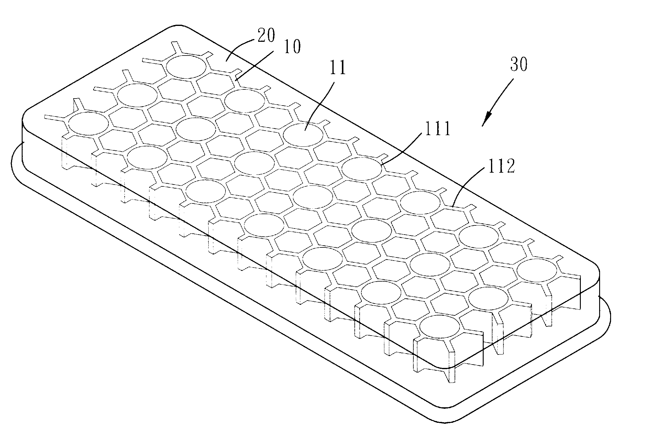
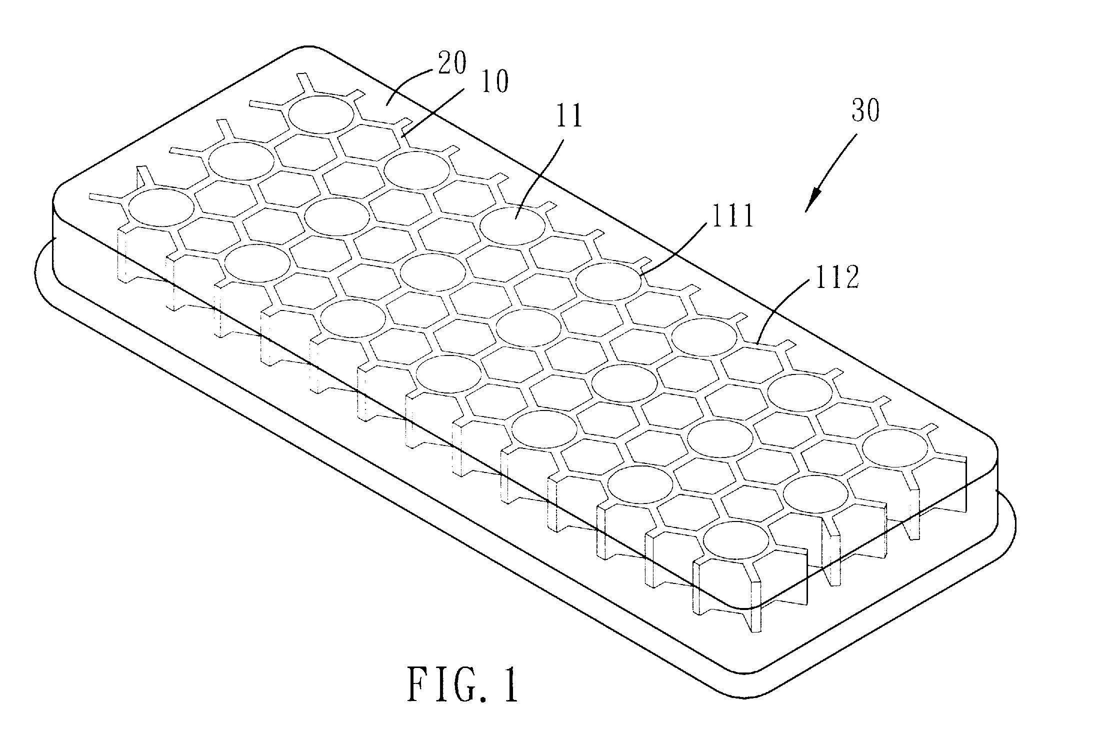
[0023]Please refer to FIGS. 1 to 4 for the present invention. A soft cushion structure includes a soft foaming resilient supportive body 10 and a soft elastomer 20 which is combined with the supportive body 10 to form a composite structure 30.

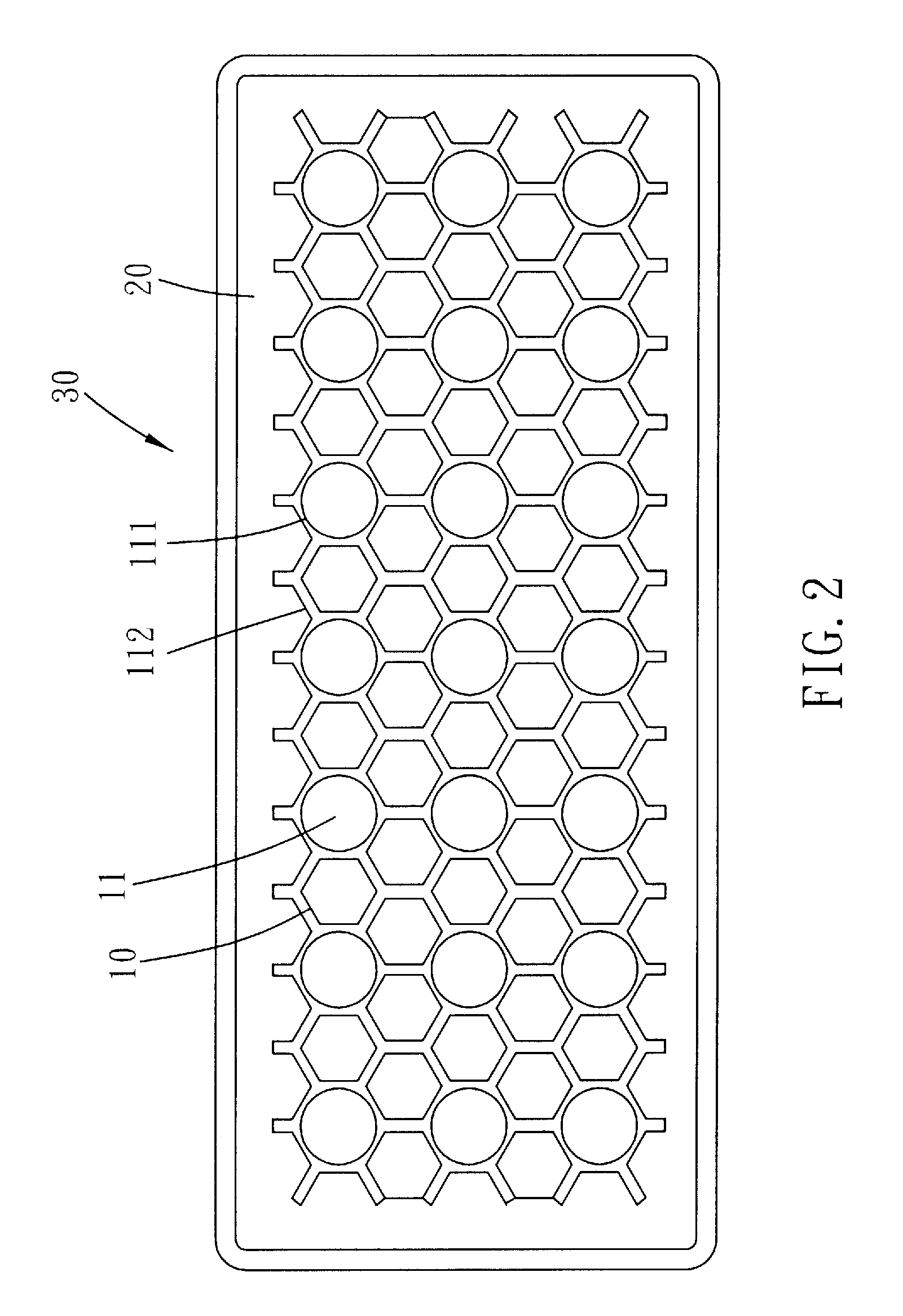
[0024]The soft foaming resilient supportive body 10 has one or more penetrating holes 11. More particularly, the holes 11 penetrate the supportive body 10 along the direction of its thickness. The supportive body 10 is formed with an upper gel room 12 and an under gel room 13, in which the holes 11 communicate the upper and under gel rooms 12 and 13. The profile of each holes 11 is circular or other geometric shaped to correspond to the stress or strain requirement of the composite structure 30. As shown in FIG. 3, the supportive body 10 has a plurality of holes 11 arranged into a honeycomb configuration. The holes 11 include round holes 111 and hexagonal holes 112. The round holes 111 are spaced arranged to form a matrix in which the distance ...

second embodiment

[0028]Please refer to FIGS. 6 and 7 for the present invention. In this embodiment, the soft elastomer 20 substantially corresponds to the configure of the foot, and the supportive body 10 has a thenar portion 14, a heel portion 15 and a connecting portion 16 which connects the thenar and heel portions 14 and 15. The thenar portion 14 has several holes 113 corresponding to the toes, and the heel portion 15 has a larger-diametered hole 114 corresponding to the heel. The soft elastomer 20 covers a main part of the upper surface of the supportive body 10, and the soft elastomer 20 is also completely filled in the holes 113 and 114 and laterally extends into the gel rooms 12 and 13 around the holes 113 and 114. As such, the soft elastomer 20 tightly combines with the supportive body 10 and has sufficient space to enable the slightly flowing strain while being pressed upon. For example, as the user stands on the soft elastomer 20 of the upper gel room 12, the weight of the user will make ...

third embodiment

[0030]Refer to FIG. 8 for the present invention. Only one hole 11 is presented on the soft foaming resilient supportive body 10, while the soft elastomer 20 is still filled in the hole 11 and the gel rooms 12 and 13 so as to combine the soft elastomer 20 with the supportive body 10 to form a composite structure 30. The soft elastomer 20, however, does not fully fill the under gel room 13, and a semispherical groove 131 (or other geometric or irregular shaped groove) is left unfilled in the under gel room 13. When the composite structure 30 load a compression stress f1, the soft elastomer 20 generates the slightly flowing strain to function the stress-strain compensation mechanism, and a part of the soft elastomer 20 will be pushed into the unfilled semispherical groove 131 to further release the pressure. Meanwhile, the supportive body 10 generates the compression strain as well as sheer strain to function the stress-strain compensation mechanism thereof, in which the compression st...


PUM

PropertyMeasurementUnit
softaaaaaaaaaa
elasticaaaaaaaaaa
stressaaaaaaaaaa

Abstract

A soft cushion structure of the present invention includes a soft foaming resilient supportive body and a soft elastomer. The soft foaming resilient supportive body has one or more penetrating holes which communicate upper and under gel rooms disposed on the soft foaming resilient supportive body. The soft elastomer is filled in the holes and at least a part of the upper and under gel rooms respectively, so as to combine the soft elastomer with the soft foaming resilient supportive body to form a composite structure.

Description

BACKGROUND OF THE INVENTION[0001]1. Field of the Invention[0002]The present invention relates to a soft cushion structure substantially consists of a soft foaming resilient supportive body and a soft elastomer.[0003]2. Description of the Prior Art[0004]A cushion structure is well discussed, such as disclosed in U.S. Pat. No. 4,654,983 and U.S. Pat. No. 5,367,792. The '983 patent discloses a sole construction including a shell and a core encapsulated within the shell. The core is made of low density PU or EVA, and the shell is made of high density PU. On the other hand, the '792 patent discloses a shoe sole construction including a shell, made of polyester elastomer, PU or EVE, and a filler, such as air, fluid or synthetic foam, stuffed in the shell.[0005]The common features of the above mentioned cushion structure is that the core (or filler) thereof is less supportive than the shell. That is, the core is mainly stuffed in the shell to elevate the property of shock absorption and cu...

Claims


Application Information

Patent Timeline
Patent Type & Authority Applications(United States)
IPC IPC(8): B32B3/10
CPCA43B1/0009Y10T428/24273A43B13/189A43B13/187
Inventor KUO, CHUN-FU
Owner KUO CHUN FU
Why Eureka
Try Eureka