
Inclinometer

a technology of inclinometer and horizontal line, which is applied in the direction of solid separation, instruments, surveying and navigation, etc., can solve the problem that inclinometers that require a horizontal line of sight may not be practical for a partially submerged sluice box

Inactive Publication Date: 2011-03-24
FINLEY JOSEPH B
View PDF23 Cites 2 Cited by
  • Summary
  • Abstract
  • Description
  • Claims
  • Application Information

AI Technical Summary

Benefits of technology

[0007]Embodiments of the invention provide an inclinometer that can overcome one or more of the aforementioned limitations. Embodiments of the invention are compact, can be easily read with a vertical line or horizontal of sight, and / or readily convey a preferred range of incline angles for an operational sluice box.

Problems solved by technology

Inclinometers that require a horizontal line of sight may not be practical for a partially-submerged sluice box.

Method used


Image

  • Inclinometer
  • Inclinometer
  • Inclinometer

Examples


Embodiment Construction

[0022]Embodiments of the invention now will be described more fully with reference to FIGS. 1 to 12, in which embodiments of the invention are shown. This invention may, however, be embodied in many different forms and should not be construed as limited to the embodiments set forth herein. Rather, these embodiments are provided so that this disclosure will be thorough and complete, and will fully convey the scope of the invention to those skilled in the art.

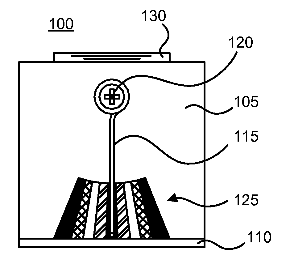
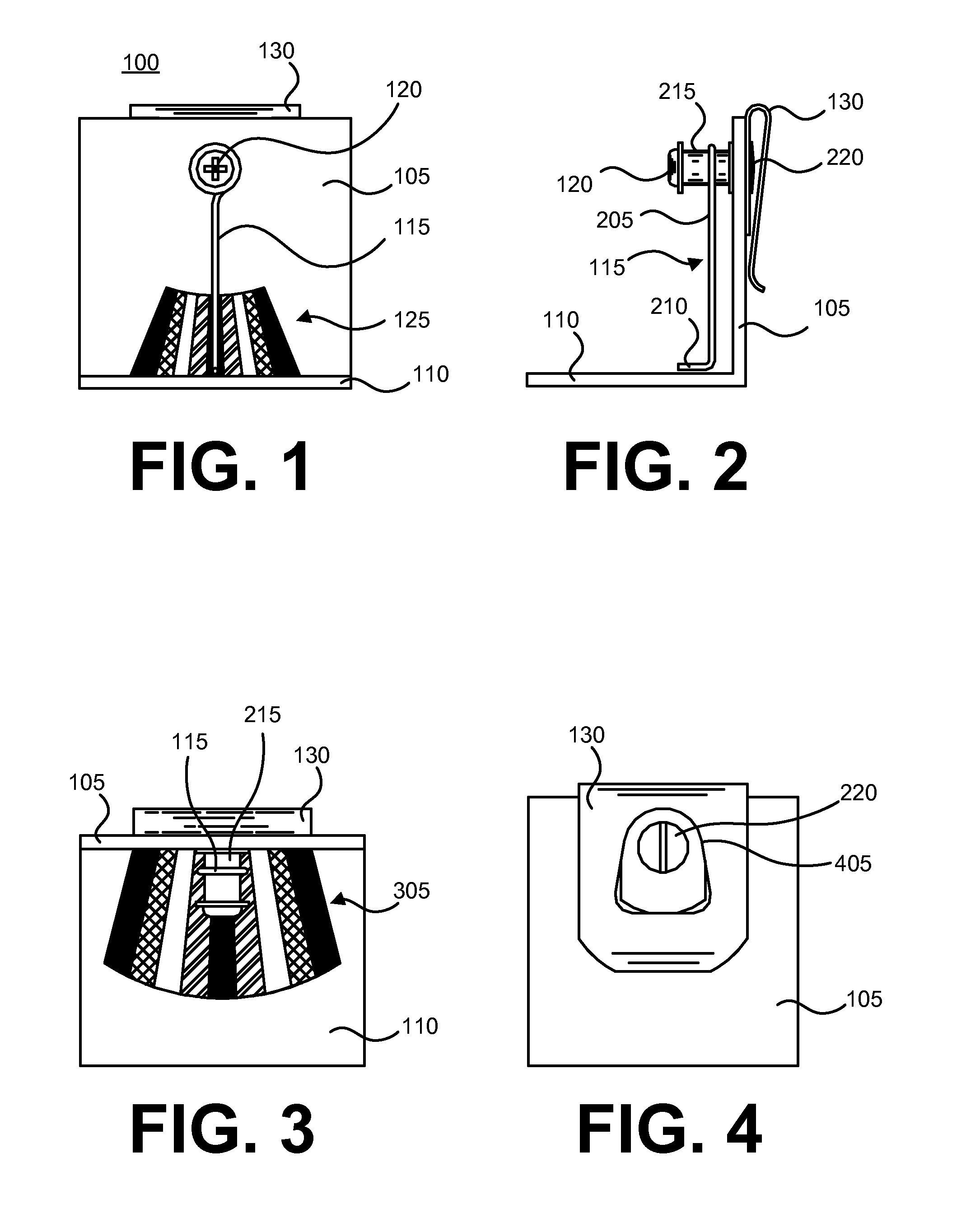
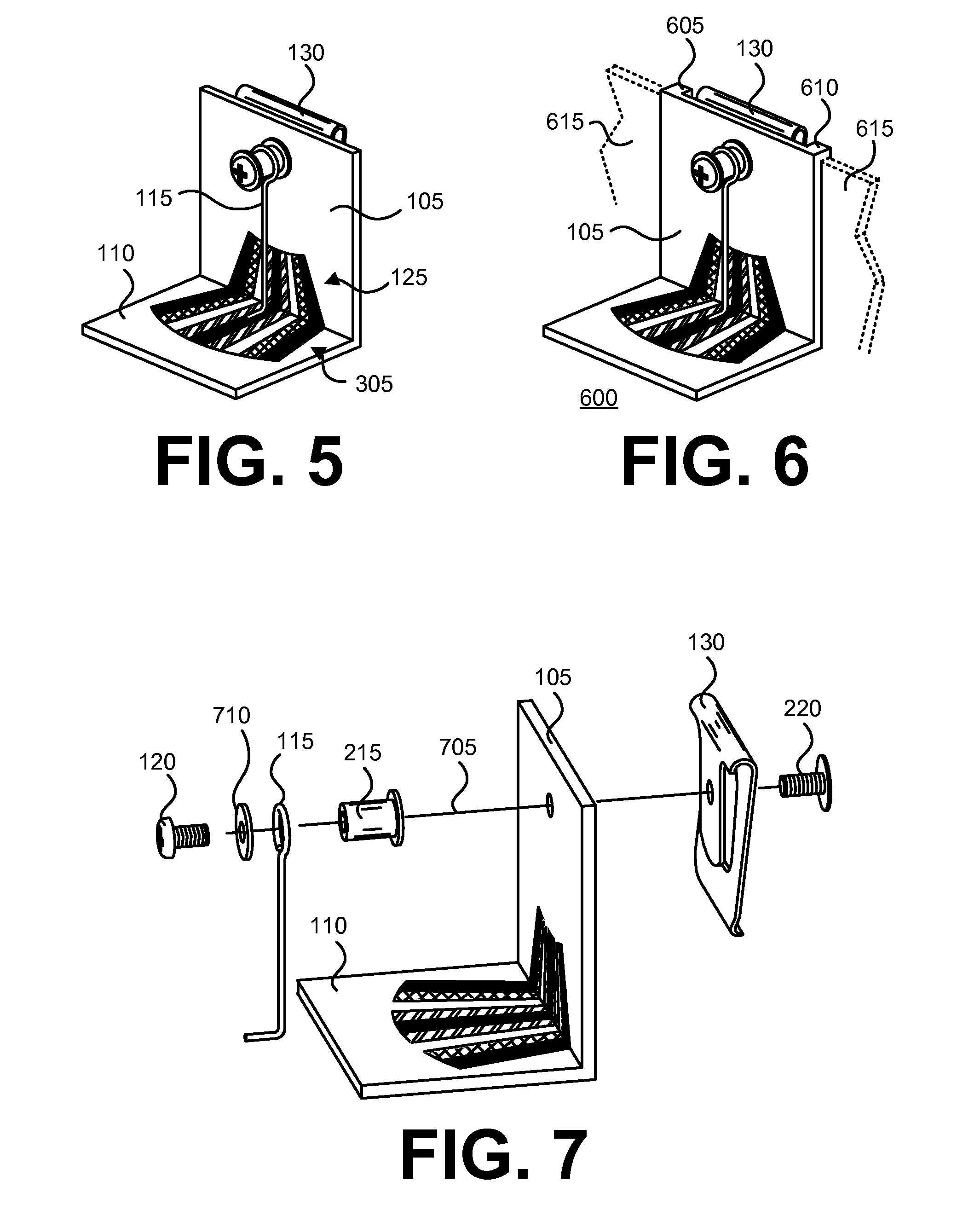
[0023]FIG. 1 is a front elevation view of an inclinometer, according to an embodiment of the invention. As shown therein, an L-shaped body of an inclinometer 100 includes a side 105 portion in a first plane that is orthogonally disposed with respect to a second plane associated with a floor 110 portion. A pendulum 115 if movably affixed to a front surface of the side 105, in part, via a face retaining screw 120. A portion of the pendulum 115 is disposed in proximity of a side scale 125. The side scale 125 is disposed on the front...


PUM


Abstract

Embodiments of the invention provide an inclinometer that is compact, can be easily read with a vertical or horizontal line of sight, and / or readily convey a preferred range of incline angles for an operational sluice box.

Description

BACKGROUND AND SUMMARY[0001]1. Field of the Invention[0002]The invention relates generally to an inclinometer, and more particularly, but without limitation, to an inclinometer that is configured to measure the incline of a sluice box.[0003]2. Description of the Related Art[0004]Placer mining involves the gravitational separation of gold or other precious metals from alluvium. One known placer mining technique is to utilize a sluice. A sluice is a flat-bottomed trough with open ends. A sluice typically includes riffles, or traps, along a bottom interior surface. In operation, the sluice is disposed at an angle so that water (from a stream or other source) can flow into a head end of the sluice and exit at a tail end. Alluvium is added to the water at the head end, and the resulting slurry flows toward the tail. Within an optimal range of incline angle, volume, and flow rate, the sluice entraps heavier precious metals in the riffles and discharges lighter gangue at the tail end.[0005...

Claims


Application Information

Patent Timeline
IPC IPC(8): G01C9/10G01C9/12
CPCG01C9/12B03B5/06
Inventor FINLEY, JOSEPH B.
Owner FINLEY JOSEPH B
Learn More