

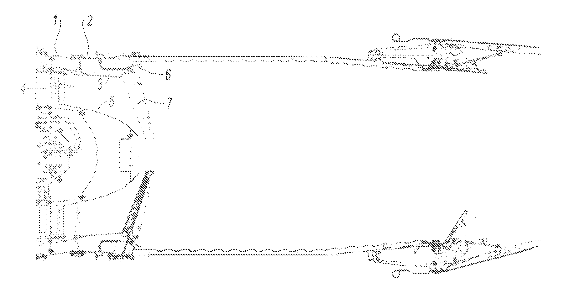
Flame-holder device comprising an arm support and a heat-protection screen that are in one piece
a technology of heat-protection screen and arm support, which is applied in the direction of continuous combustion chamber, lighting and heating apparatus, combustion process, etc., can solve the problems of loss of tightening between the two parts, source of stress and fatigue, and the need to provide for cooling, so as to limit the range of movement of the screen and promote the attenuation of vibrations
- Summary
- Abstract
- Description
- Claims
- Application Information
AI Technical Summary
Benefits of technology
Problems solved by technology
Method used
Image

Examples
first embodiment
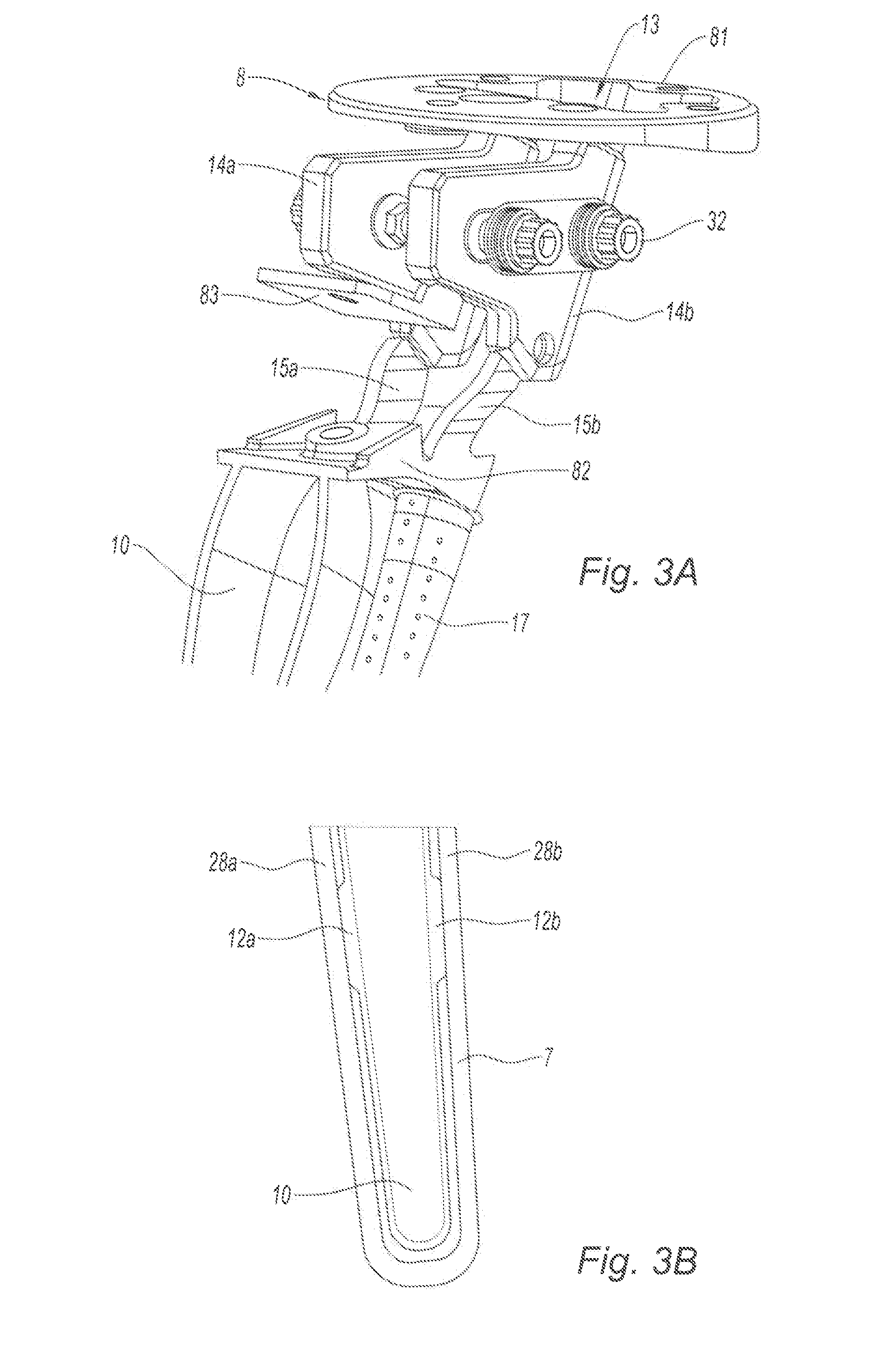
[0064] the protection screen 10 comprises bosses 12a, 12b to provide a prestress with the internal wall of the flame-holder arm 7, the bosses forming a local extra thickness in the wall of the protection screen 10. With reference to FIG. 3B, the protection screen 10 comprises two bosses 12a, 12b made on the external lateral walls of the protection screen 10, the bosses 12a, 12b extending toward the outside of the protection screen 10, in the direction opposite to the cavity of the protection screen 10. The bosses 12a, 12b in this instance extend longitudinally, in the length of the protection screen 10, and have a predetermined thickness in order to prestress the protection screen 10 in the flame-holder arm 7 while making an air gap of sufficient thickness to prevent the transfer of heat between the protection screen 10 and the flame-holder arm 7. The length of the bosses 12a, 12b is the result of a compromise between a considerable length improving the prestress and limiting the tr...
second embodiment
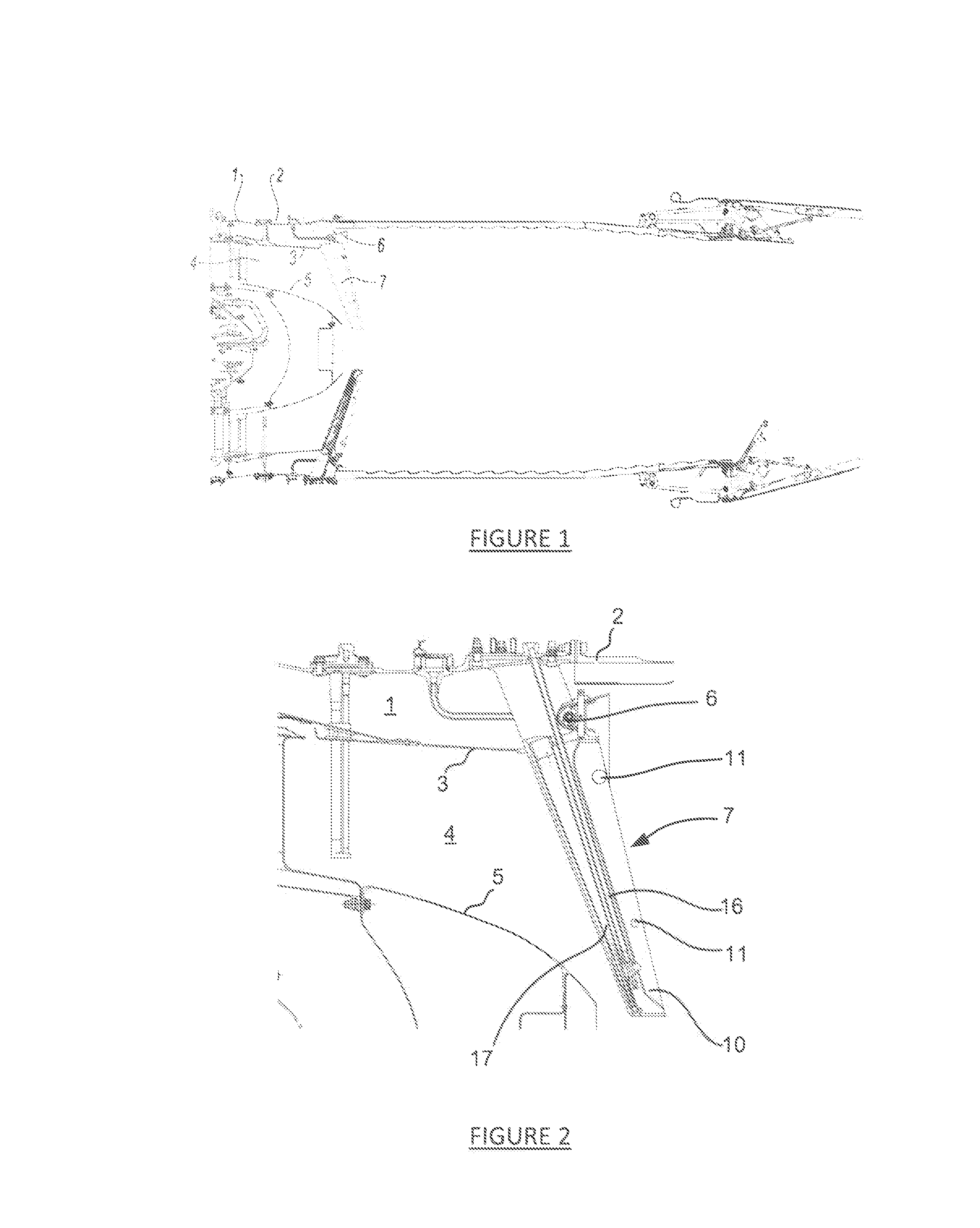
[0077]In a second embodiment, with reference to FIG. 4, the device comprises a retention shoe 18, placed in the cavity of the flame-holder arm 7, arranged to maintain an air gap between the flame-holder arm 7 and the protection screen 10. Such a shoe 18, known for example through patent application FR 2928202, comprises a flat body with radial orifices in order to allow the passage and the retention of the fuel injector 16 and of the ventilation tube 17. The shoe 18 also comprises spacing lugs arranged in order to extend between the lateral walls of the protection screen 10 and of the arm 7.
[0078]With reference to FIG. 4, the lugs are attached securely to the protection screen 10, said spacing lugs forming said means for prestressing the protection screen 10 in the flame-holder arm 7. The lateral walls of the protection screen 10 and of the arm 7 are then separated by an air gap corresponding to the thickness of the lugs. The lugs of the shoe make it possible, like the bosses, to ad...
PUM
 Abstract
Description
Claims
Application Information