
Heat shield and an insulating isolator for the heat shield

Active Publication Date: 2011-03-24
DANA AUTOMOTIVE SYST GRP LLC
View PDF29 Cites 32 Cited by
  • Summary
  • Abstract
  • Description
  • Claims
  • Application Information

AI Technical Summary

Benefits of technology

[0011]In another embodiment, a heat shield for thermal and acoustical insulation of an object has at least one metallic sheet. At least two disk apertures pass through the at least one metallic sheet. Two metallic disks are located in the area of at least one of the two disk apertures. The metallic disks are connected to each other, have

Problems solved by technology

Such high temperatures can create significant risks of damage to components, such as electronic components, nested under the hood.
The different relative movement of the manifold and heat shield can make alignment of the two difficult.
However, the rest of the heat shield may not be exposed to such severe conditions.

Method used


Image

  • Heat shield and an insulating isolator for the heat shield
  • Heat shield and an insulating isolator for the heat shield
  • Heat shield and an insulating isolator for the heat shield

Examples


Embodiment Construction

[0034]It is to be understood that the invention may assume various alternative orientations and step sequences, except where expressly specified to the contrary. It is also to be understood that the specific devices and processes illustrated in the attached drawings, and described in the following specification are simply exemplary embodiments of the inventive concepts defined in the appended claims. Hence, specific dimensions, directions or other physical characteristics relating to the embodiments disclosed are not to be considered as limiting, unless expressly stated otherwise.

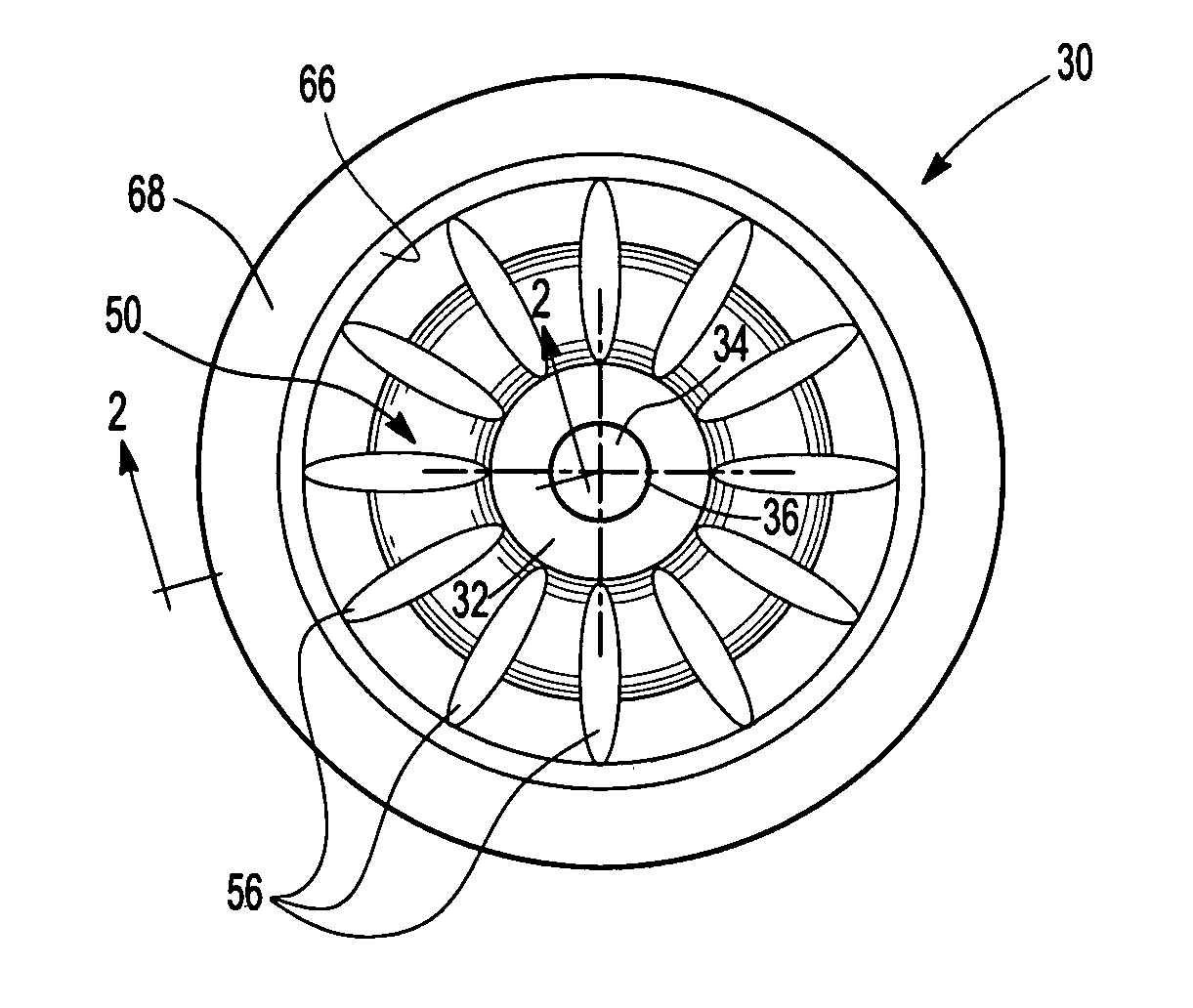
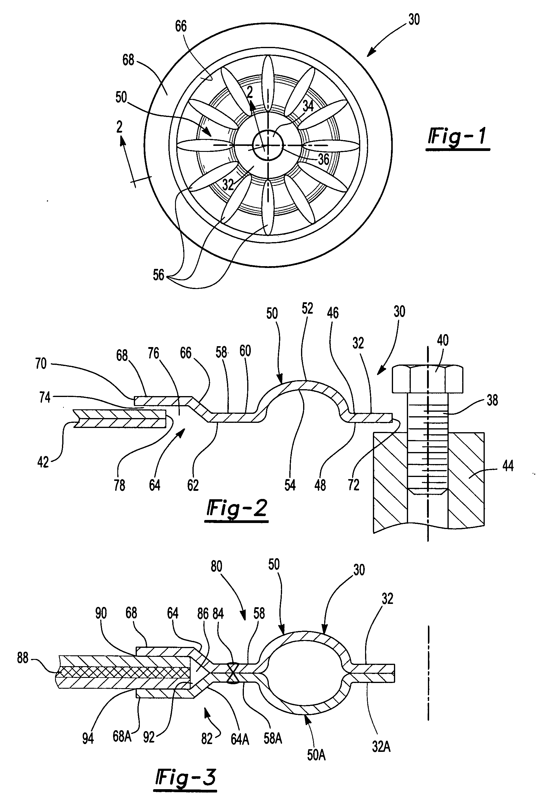
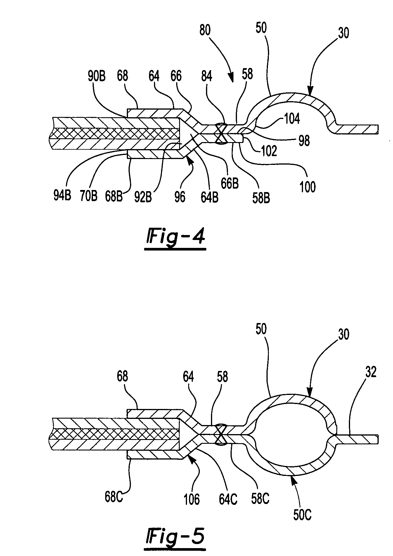
[0035]Referring now to FIGS. 1 and 2, one embodiment of an insulating isolator 30 of the present invention is depicted. In this embodiment, the isolator 30 has a first land 32 that continuously surrounds a fastener aperture 34. The first land 32 comprises an inner edge 36 that forms the perimeter of the fastener aperture 34. In this embodiment, the perimeter is circular, however, other shapes are also permi...


PUM


Abstract

An insulating isolator for a heat shield has a unitary first land, a bead portion, a second land and a half bead. The first land defines a fastener aperture. In one case, a plurality of circumferentially spaced apart petals is formed in the isolator. The petals may be separated by gaps. In another case, a set of circumferentially spaced apart apertures are formed in the isolator.The heat shield may have at least two disk apertures. Two metallic disks are located in the area of at least one of the two disk apertures. The metallic disks are connected to each other, have aligned fastener openings that are smaller than the disk apertures and they are smaller than the metallic sheet. One of the metallic disks may have a bead.

Description

RELATED APPLICATIONS [0001]This application claims benefit from U.S. patent application Ser. No. 61 / 244,900 filed on Sep. 23, 2009, which is incorporated by reference in its entirety herein.FIELD OF THE INVENTION [0002]The present invention relates to a heat shield and an insulating isolator for the heat shield, such as for an internal combustion engine.BACKGROUND OF THE INVENTION [0003]In today's modern vehicles, the exhaust manifolds of internal combustion engines can reach under-the-hood temperatures in the neighborhood of 1600 degrees Fahrenheit. Such high temperatures can create significant risks of damage to components, such as electronic components, nested under the hood. Thus, protection is warranted, and has been provided via use of heat shields designed to cover up, or partially block, and hence to insulate, exhaust manifolds and other heat generating components.[0004]Manifold heat shields conventionally mount to the exhaust manifold of an internal combustion engine with a...

Claims


Application Information

Patent Timeline
IPC IPC(8): E04B1/88B32B3/10
CPCB60R13/0876Y10T428/24322Y10T428/24273F01N2260/20
Inventor OXENKNECHT, ERNESTSCHWEIGGART, FRANZSCHIMMELE, OLIVERGIAIMI, GIACOMO
Owner DANA AUTOMOTIVE SYST GRP LLC
Learn More