Corrosion-protected, self-drilling anchor and anchor subunit and method for the production thereof

a self-drilling anchor and self-drilling technology, which is applied in the direction of screw threads, mechanical equipment, other domestic objects, etc., can solve the problems of denying the use of self-drilling anchors in an environment with a high corrosion risk, damage to corrosion protection, and inability to meet the requirements of corrosion protection, etc., to achieve a wide range of vibration-free advance, high quality, and easy loosening of the broken substra

Inactive Publication Date: 2011-03-24
DYWIDAG SYST INT GMBH (DE)
View PDF15 Cites 18 Cited by
  • Summary
  • Abstract
  • Description
  • Claims
  • Application Information

AI Technical Summary

Benefits of technology

[0011]Thanks to the invention, this bias has been overcome and a self-drilling anchor has been provided that also meets the requirements of increased corrosion protection. For this purpose, the invention provides a solution that assures corrosion protection both in the area of the hollow bars and in the joint area. This is achieved by an axial continuous combination of sheathings and couplers, which represent a first barrier against external, corrosion-causing substances. The hollow space formed thereby to the hollow bar element is filled in each case with a corrosion protection compound, which forms the second barrier against corrosion, which is why the term double corrosion protection is used. An anchor of the invention therefore combines for the first time the advantages of a self-drilling anchor with the advantages of a double corrosion-protected anchor or pile.
[0013]According to an embodiment of the invention, in each case, an adapter is provided at the end of the sheathing, which even during the manufacturing of the prefabricated anchor subunits seals the openings on the face side of the sheathings tightly against the hollow bar and simultaneously enables tight attachment of the coupler. For this purpose, the adapter preferably has a cylindrical seat, onto which the coupler can be pushed axially, whereby in the insertion area means for securing the position and sealing of the coupler can be arranged, for example, in the form of a circumferential bead. In order not too increase the outside diameter of the self-drilling anchor in this regard, it is advantageous to provide a radial recess in the area of the cylindrical seat for receiving the coupler.
[0015]The factory production of these anchor subunits offers the great advantage that they can be produced under invariable optimal conditions and independent of climate effects. Thereby, a constant high quality of the thus produced anchor subunits is possible with a corresponding quality gain in the finished self-drilling anchor. Moreover, the corrosion protection compound within the sheathing can be matched, without consideration of the later grouting of the borehole, specifically to the requirements of optimal corrosion protection, for example, by its special composition and the manner of its introduction. For the grouting of the borehole after the anchor has been installed, a cement grout can then be used, likewise optimized for this intended application.
[0016]Another embodiment of the invention, moreover, has a drill bit with a nozzle with outlet openings slantingly facing forward in the drilling direction. The jet stream emerging from the nozzle breaks up the substrate in front of the nozzle and can even loosen and pulverize it with use of high pressures. The arrangement of a nozzle with radial outlet openings can be provided alternatively or cumulatively for the same purpose. This produces the advantage that the broken up substrate can be loosened more easily for the drill bit, so that a largely vibration-free advance is possible. Thereby, the risk of crack formation in the area of the preinjected corrosion protection of the hollow bar anchor is minimized.

Problems solved by technology

On the one hand, there were concerns that the factory preinjected and already hardened corrosion protection compound, usually a cement- or resin-bound grout or suspension, would form cracks between the sheathing and anchor bar during the drilling process and the corrosion protection would be damaged thereby; on the other hand, there was no satisfactory solution to assure corrosion protection also in the joint area of two hollow bars.
Use in an environment with a high corrosion risk therefore continued to be denied to the self-drilling anchor.

Method used


Image

  • Corrosion-protected, self-drilling anchor and anchor subunit and method for the production thereof
  • Corrosion-protected, self-drilling anchor and anchor subunit and method for the production thereof
  • Corrosion-protected, self-drilling anchor and anchor subunit and method for the production thereof

Examples


Embodiment Construction

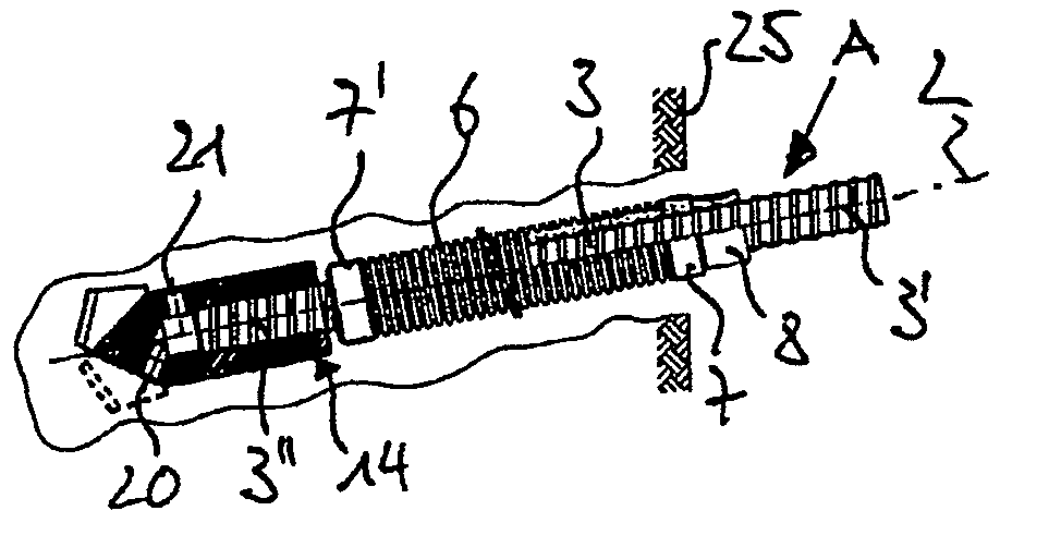
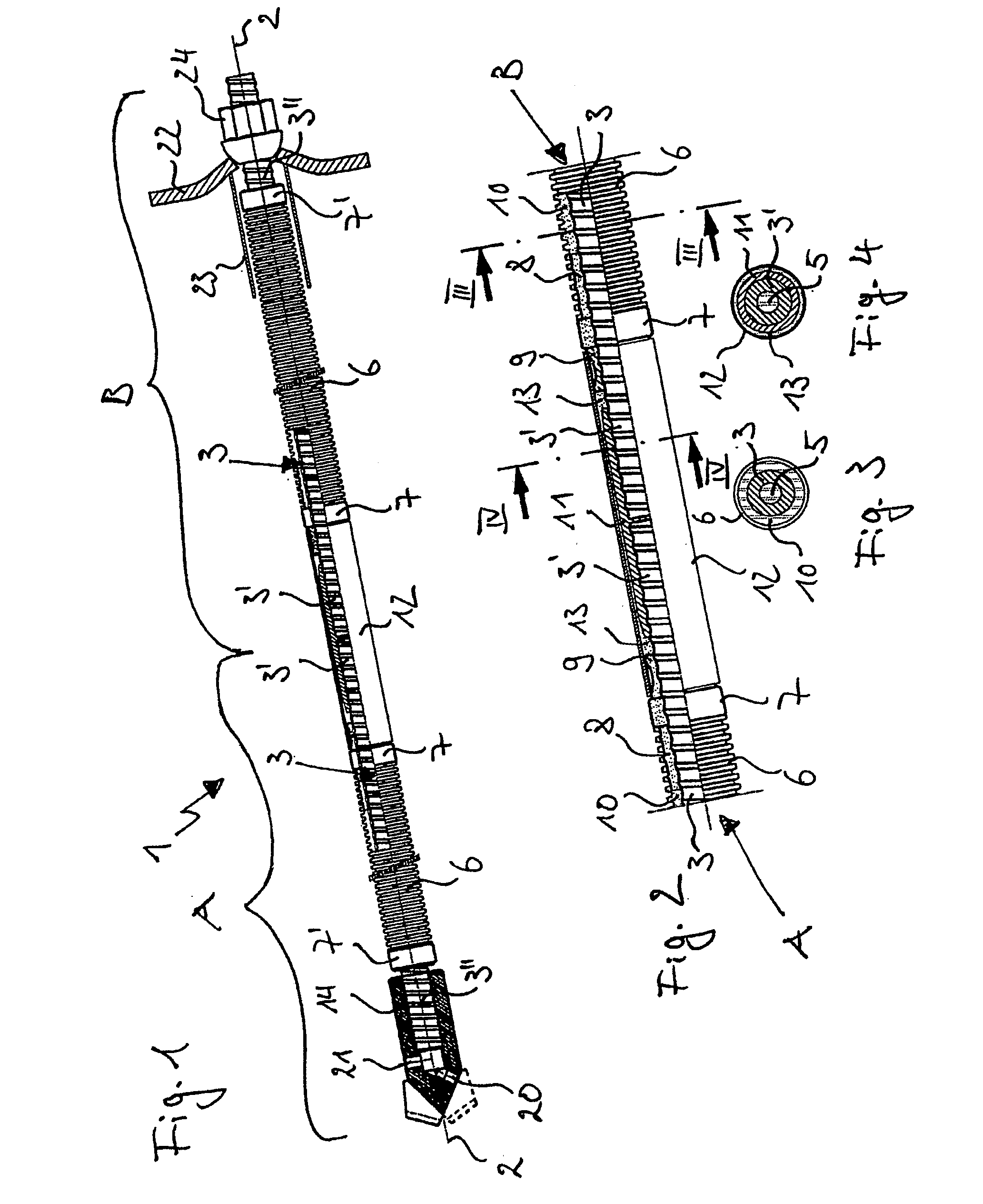
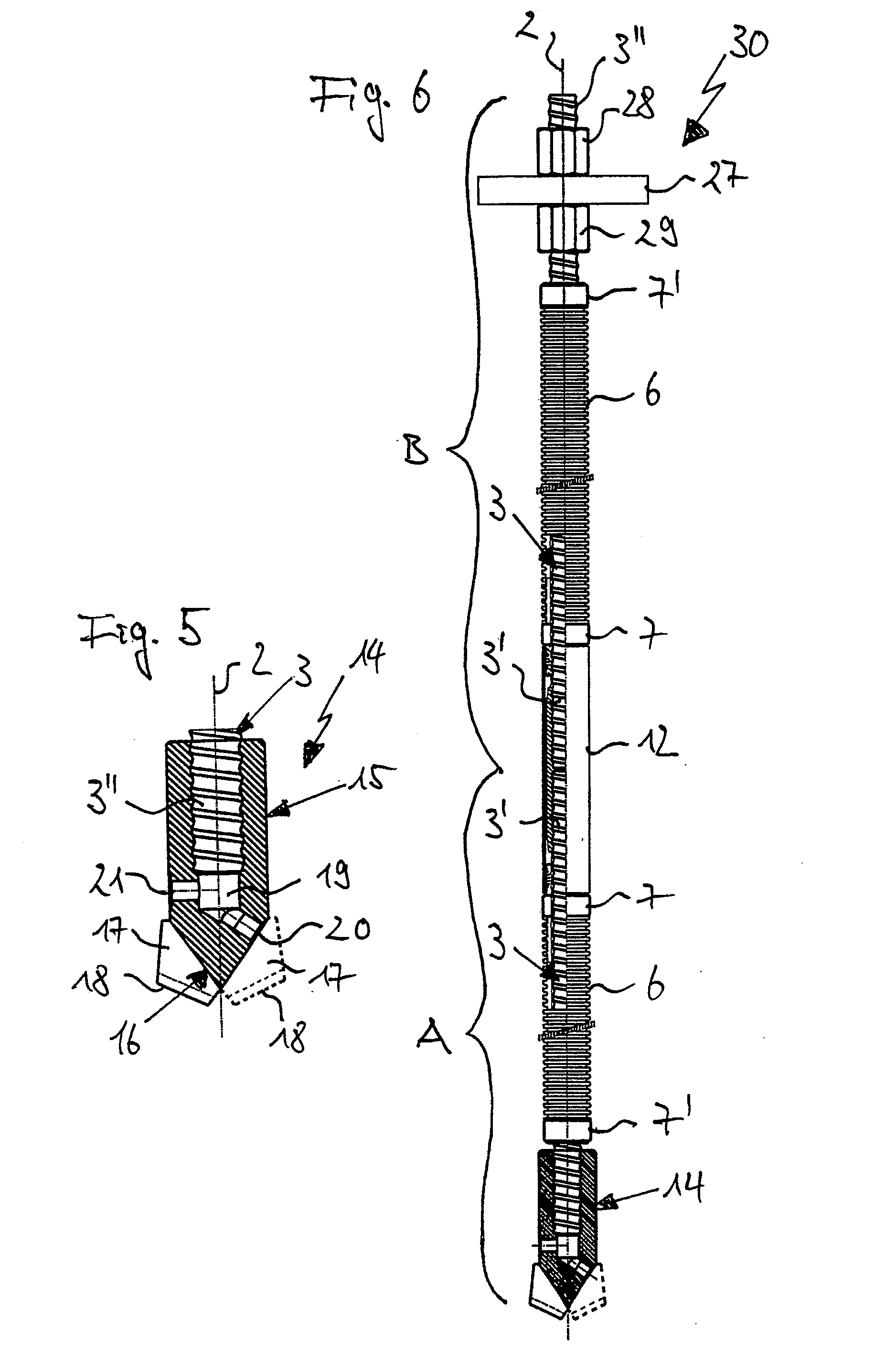
[0026]A self-drilling anchor 1 of the invention is shown in a general view in FIG. 1, as it can be used advantageously in injectable soils. Anchor 1 in the present example has two factory-prefabricated subunits A and B with substantially the same structure, which are butted form-fittingly along the longitudinal anchor axis 2. The length of units A and B can be varied between 1 m and 6 m as required. An anchor 1 of the invention with the desired total length can be produced by stringing together of a predefined number of subunits A, B each with a predefined length.

[0027]The structure of subunits A, B is evident, moreover, from FIGS. 2, 3, and 4. Evident is a hollow bar element 3, which is provided with an outside thread 4 over its entire length and which has an axial through-hole 5 in the area of its longitudinal axis 2. Hollow bar element 3 is surrounded over its entire length, except for its end sections 3′, 3″, by corrugated sheathing 6 at a clearance distance. The two ends of cor...


PUM

PropertyMeasurementUnit
lengthaaaaaaaaaa
lengthaaaaaaaaaa
areaaaaaaaaaaa

Abstract

A corrosion-protected, self-drilling anchor and an anchor subunit and to a method for the production thereof is provided. A self-drilling anchor of the invention includes a number of anchor subunits, each with a hollow bar element, which are connected together by the formation of an axial bell butt joint to form a connected pull and pressure member. The first subunit t its end has a drill bit and the subunit is connected non-rotatably with its end to a drilling and injection device. It is provided according to the invention that each hollow bar element is surrounded by a sheathing except for its end sections and the annular gap between the sheathing and hollow bar element is grouted with a first corrosion protection compound. A coupler in the area of the bell butt joint fits tightly against the sheathings of the two hollow bar elements which are part of the bell butt joint. The hollow space between the coupler and hollow bar elements is filled with a second corrosion protection compound. A method of the invention provides for the prefabrication of a number of anchor subunits at the factory to drill these into the substrate at the site of the anchor to be produced and thereby for connecting them together with the formation of bell butt joints, whereby in the area of the bell butt joint a coupler fits tightly against the ends of two neighboring sheathings and the hollow space between the coupler and hollow bar element is filled with a second corrosion protection compound.

Description

[0001]This nonprovisional application is a continuation of International Application No. PCT / EP2009 / 001994, which was filed on Mar. 18, 2009, and which claims priority to German Patent Application No. DE 10 2008 014 700.1, which was filed in Germany on Mar. 18, 2008, and which are both herein incorporated by reference.BACKGROUND OF THE INVENTION[0002]1. Field of the Invention[0003]The invention relates to a corrosion-protected, self-drilling anchor, a method for the production thereof, and a prefabricated anchor subunit.[0004]2. Description of the Background Art[0005]Ground and rock anchors and piles are used in underground construction whenever it is necessary to transmit forces in the region of the anchor or pile head to deeper soil strata. This applies equally to tension-loaded anchors and nails and to pressure- or tension-loaded piles. For this purpose, anchors, nails, or piles have a supporting member that is brought into a force-fit connection with the surrounding substrate in...

Claims


Application Information

Patent Timeline
Patent Type & Authority Applications(United States)
IPC IPC(8): E21D20/02E02D5/80B21H3/02
CPCE21D2021/0053E21D21/0013E21D21/0053
Inventor SCHMIDT, FRANK
Owner DYWIDAG SYST INT GMBH (DE)
Why Eureka
Try Eureka