Two-stage rotary expander, expander-integrated compressor, and refrigeration cycle apparatus

Inactive Publication Date: 2011-03-24
PANASONIC INTELLECTUAL PROPERTY MANAGEMENT CO LTD
View PDF11 Cites 6 Cited by
  • Summary
  • Abstract
  • Description
  • Claims
  • Application Information

AI Technical Summary

Benefits of technology

[0017]The two-stage rotary expander of the present invention includes a variable vane mechanism for controlling the movement of the first vane. By the action of the variable vane mechanism, the first vane is spaced from the first piston during the period P2, which is a part of the period of one rotation of the shaft, so that the working fluid in the first suction space can flow directly into the first discharge space. When the ratio (P2/P1) changes under the control of the movement of the first vane, the suction volume (volumetric flow rate) of the expansion mechanism also changes. That is, the constraint of constant density ratio can be avoided. In addition, since the power can be recovered from the entire amount of the working fluid, a high power recovery efficiency can be achieved.
[0018]Here, the minimum value of the period P2 may be zero. When the period P2 is zero, the first vane and the first piston are in contact with each other all the time, and thus the suction volume of the two-stage rotary expander is minimized. More specifically, the variable vane mechanism controls the movement of the first vane so that one of the following (a) and (b) is achieved.
[0019](a) The variable vane mechanism controls the movement of the first vane

Problems solved by technology

That is, the temperature and pressure of the working fluid at Point C cannot be controlled freely.
Therefore, if the temperature and pressure cannot be controlled freely, it is difficult to operate the refrigeration cycle apparatus efficiently.
This method, however, has a problem in that the expansion energy of the working fluid flo

Method used


Image

  • Two-stage rotary expander, expander-integrated compressor, and refrigeration cycle apparatus
  • Two-stage rotary expander, expander-integrated compressor, and refrigeration cycle apparatus
  • Two-stage rotary expander, expander-integrated compressor, and refrigeration cycle apparatus

Examples


first embodiment

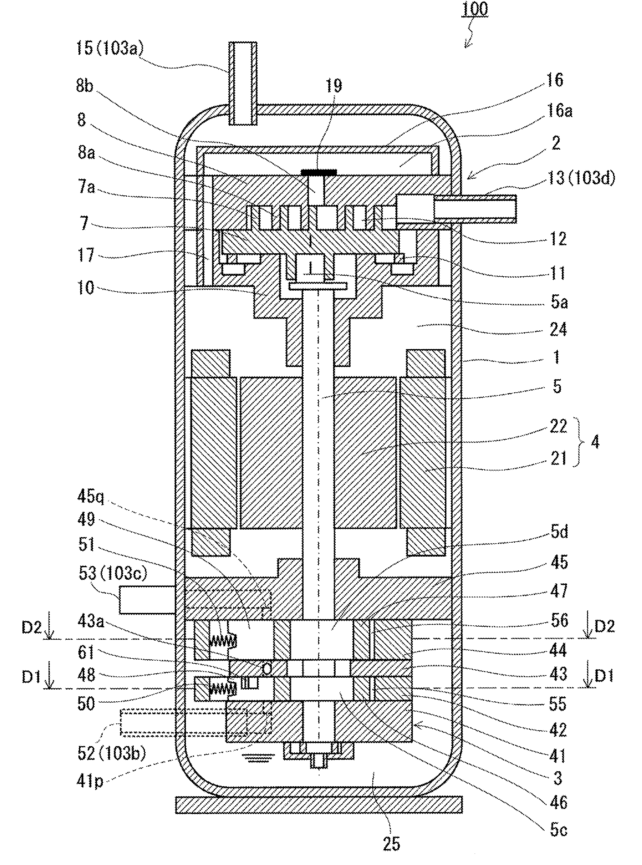
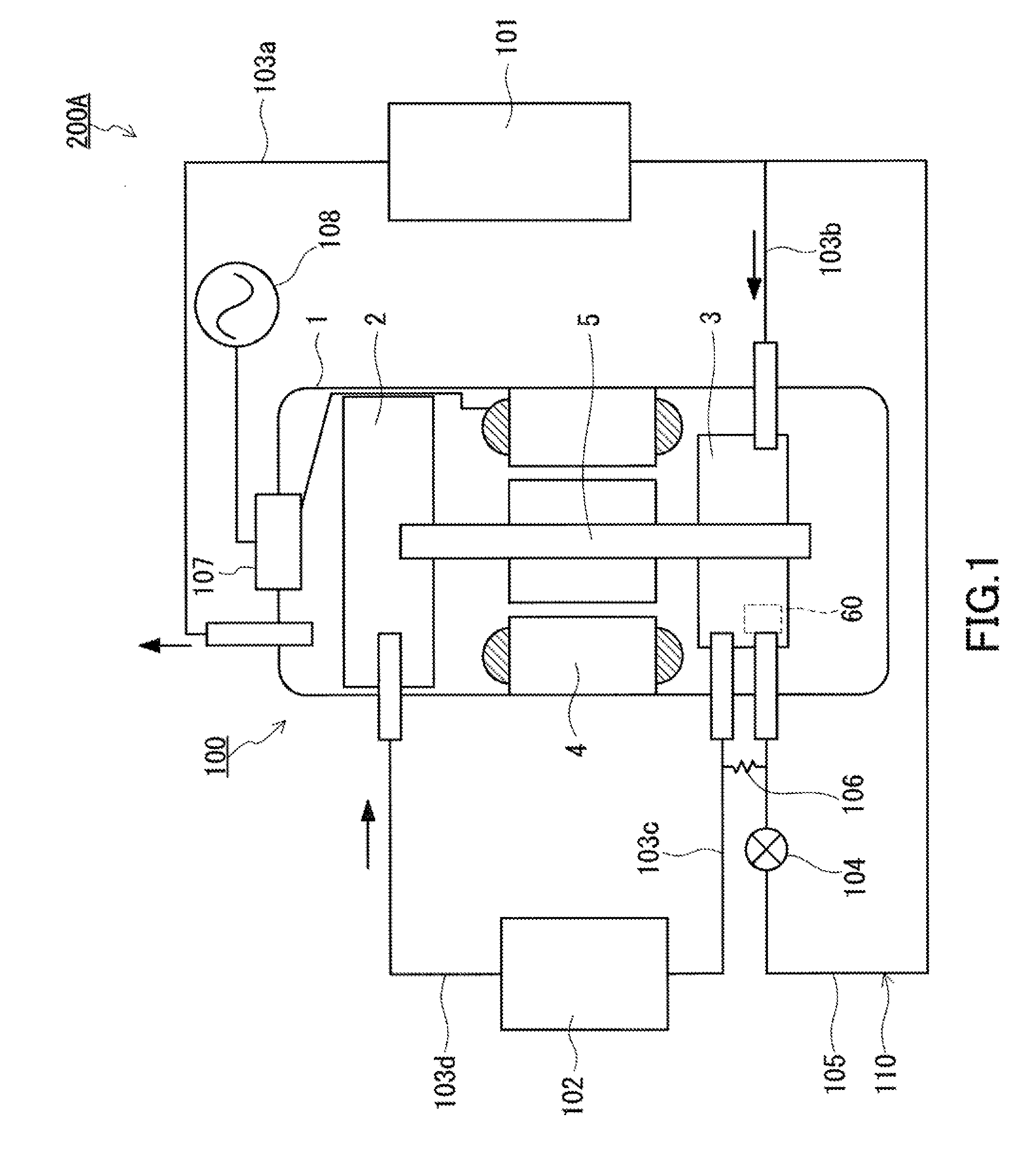
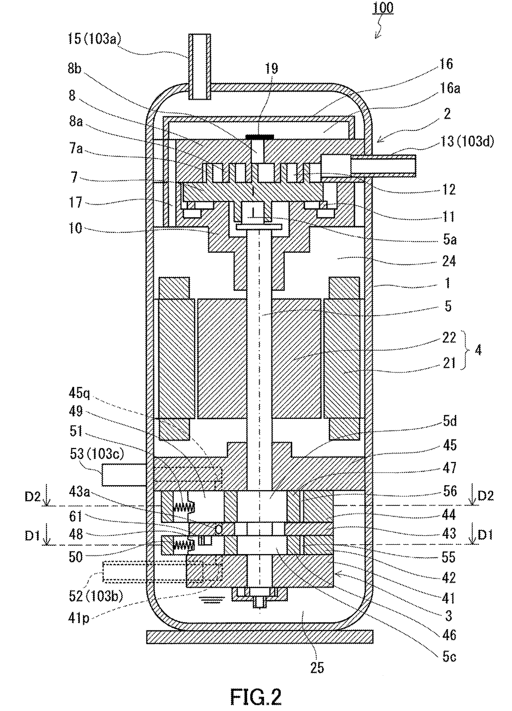
[0059]As shown in FIG. 1, a refrigeration cycle apparatus 200A of the present embodiment includes a compression mechanism 2, a radiator 101, an expansion mechanism 3, an evaporator 102, and a plurality of pipes 103a to 103d for connecting these components to each other so as to form a refrigerant circuit. The compression mechanism 2 and the expansion mechanism 3 are coupled together by a shaft 5 so as to constitute an expander-integrated compressor 100. The basic operation of the refrigeration cycle apparatus 200A is as described in the background art.

[0060]The expansion mechanism 3 of the expander-integrated compressor 100 is provided with a variable vane mechanism 60. The variable vane mechanism 60 has a function of changing the volume (volumetric flow rate) of a working fluid to be drawn into the expansion mechanism 3 during one rotation of the shaft 5. In other words, it has a function of changing the suction volume of the expansion mechanism 3. The constraint of constant densit...

second embodiment

[0108]FIG. 8 shows a refrigeration cycle apparatus according to the second embodiment of the present invention. A refrigeration cycle apparatus 200B of the present embodiment includes, instead of the pressure supply circuit 110, a pipe 112 connecting the pipe 103c and the variable vane mechanism 60. This refrigeration cycle apparatus 200B is different from that of the first embodiment in that the discharge pressure of the expansion mechanism 3 is supplied to the pressure chamber 76a of the variable vane mechanism 60. In the following embodiments, the same components are designated by the same reference numerals, and no further description is given.

[0109]In the refrigeration cycle apparatus 200B, the position of the stopper 61 changes according to the discharge pressure of the expansion mechanism 3, and thus the ratio (P2 / P1) changes. The lower the discharge pressure of the expansion mechanism 3 is, the higher the stopper 61 is positioned. As a result, the period P2 in which the firs...

third embodiment

[0110]The actuator of the variable vane mechanism is not limited to a fluid pressure actuator. FIG. 9 is a configuration diagram showing a refrigeration cycle apparatus using an electric actuator as an actuator of the variable vane mechanism. This refrigeration cycle apparatus 200C has an expander-integrated compressor 100C. The expansion mechanism 3 in the expander-integrated compressor 100C is provided with a variable vane mechanism 60C including an electric actuator. The electric actuator of the variable vane mechanism 60C is connected to an external controller 70. The operation of the electric actuator can be controlled by the external controller. The refrigeration cycle apparatus 200C has an advantage in that the pressure supply circuit 110 described with reference to FIG. 1 can be omitted. Furthermore, since the positioning accuracy of the stopper can be increased easily by the electric actuator, the injection amount can be optimized more easily.

[0111]As shown in FIG. 10A and ...


PUM


Abstract

An expander-integrated compressor (100) includes: a compression mechanism (2) for compressing a working fluid; an expansion mechanism (3) for expanding a working fluid; and a shaft (5) that couples the compression mechanism (2) and the expansion mechanism (3). The expansion mechanism (3) includes a variable vane mechanism (60). The variable vane mechanism (60) controls the movement of a first vane (48) so that the ratio of a period P2 to a period P1 (P2/P1) can be adjusted, where P1 denotes the period during which the first vane (48) is in contact with a first piston (46) in the course of one rotation of the shaft (5), and P2 denotes the period during which the first vane (48) is spaced from the first piston (46) in the course of one rotation of the shaft (5).

Description

TECHNICAL FIELD[0001]The present invention relates to a two-stage rotary expander, an expander-integrated compressor, and a refrigeration cycle apparatus.BACKGROUND ART[0002]There have been proposed refrigeration cycle apparatuses in which an expander recovers the expansion energy of a working fluid, and the recovered energy is used for a part of the work of the compressor. As one of such refrigeration cycle apparatuses, a refrigeration cycle apparatus using an expander-integrated compressor is known (see Patent Literature 1).[0003]FIG. 28 shows a conventional refrigeration cycle apparatus using an expander-integrated compressor. This refrigeration cycle apparatus includes a compressor (compression mechanism) 201, a radiator 202, an expander (expansion mechanism) 203, and an evaporator 204. These components are connected to each other by pipes so as to form a main circuit 208. The compressor 201 and the expander 203 are coupled together by a shaft 207. A motor 206 for rotationally d...

Claims


Application Information

Patent Timeline
IPC IPC(8): F01C11/00
CPCF01C21/0827F04C18/0215F04C18/3562F04C23/006F01C21/0854F25B1/04F25B9/008F25B9/06F25B2400/14F04C23/008
Inventor TAKAHASHI, YASUFUMIOKAICHI, ATSUOOGATA, TAKESHITAGUCHI, HIDETOSHIHIKICHI, TAKUMIMATSUI, MASARU
Owner PANASONIC INTELLECTUAL PROPERTY MANAGEMENT CO LTD
Why Eureka
Try Eureka