Highly representative real-time simulation of an avionics system

a real-time simulation and avionics technology, applied in the field of aviation, can solve the problems of avionics simulation, the diversity of their components, and the need for processing capacity and a number of processors on the workstation used for simulation, and achieve the effect of simple, fluid and efficien

Active Publication Date: 2011-03-24
EUROCOPTER
View PDF6 Cites 43 Cited by
  • Summary
  • Abstract
  • Description
  • Claims
  • Application Information

AI Technical Summary

Benefits of technology

[0063]Against this background, it would also be useful for all of the actors involved in the simulation or needing it, to be able simultaneously to exchange information that is useful for the simulation between one another, and even to act on that information, in a manner that is simple, fluid, and efficient.
[0075]This is different from that which is made available by presently-known simulators that do not enable the communications buses in the architecture of an avionics system to be modeled in a manner that is reliable and traceable.
[0079]In embodiments putting a high demand on resources, in particular concerning the clock that drives the simulation, it is possible to use platforms that guarantee so called “hard real time”.
[0088]Thus, after being validated on the mock-up that forms a testing tool, the avionics system as tested virtually in this way must be capable of operating in a manner that is identical to the way it operates in real flight, thereby minimizing the problems or defects usually encountered during first flights or after each modification to a definition that has previously been tested on a conventional simulator.

Problems solved by technology

One of the difficulties encountered with simulations of avionics systems is the diversity of their components (e.g. the pieces of equipment, also called “equipments” in the aviation domain), and the diversity of the data formats that need to be taken into account for simulation purposes.
It can thus be understood that this wide variety of data (in particular in avionics format) for transforming into data in engineering format, and conversely for retrieving from engineering format, gives rise at present to numerous technical problems.
Another drawback at present is that the workstations used for simulations need to have processing capacity and a number of processors that are greater than the capacities and the number of processors in the avionics systems to be simulated.
Yet another drawback that is observed during simulation lies in the difficulty of incorporating changes in the avionics system and / or in its components.
As mentioned above, real time simulation of avionics systems at the present time gives rise to various technical problems, in particular when high representativity is required of the simulated avionics system.
In other words, it is difficult or even impossible in practice at the present time to obtain an abstraction, i.e. a “translation” or conversion, of these varied data streams in a manner that is simple.
As a result, it is particularly difficult with present-day simulations to represent faithfully the real architecture of an avionics system and / or to enable the system to be represented in part only.
Another problem that is presently encountered when simulating an avionics system is obtaining exhaustive and reliable definitions of the various components of the avionics system that it is desired to simulate.
In other words, it is at present difficult to obtain definitions that are consistent and exhaustive of the avionics architecture of a system that is to be simulated.
Another problem is that it is presently difficult or even impossible in practice to play back on a mock-up data that is sufficiently reliable and easy to process for the purpose of qualifying (specifying) at least one of the pieces of equipment of the avionics system.
Still another problem is to have a simulation environment that is flexible and reliable in order to monitor all of the simulation data (regardless of whether it is in engineering and / or avionics format).
One of the additional problems presently encountered with test benches is that, in practice, it is difficult to perform tests of an avionics system if any of its essential components are unavailable and / or not operational.

Method used


Image

  • Highly representative real-time simulation of an avionics system
  • Highly representative real-time simulation of an avionics system
  • Highly representative real-time simulation of an avionics system

Examples


Embodiment Construction

[0135]Embodiments and implementations of the invention are described below.

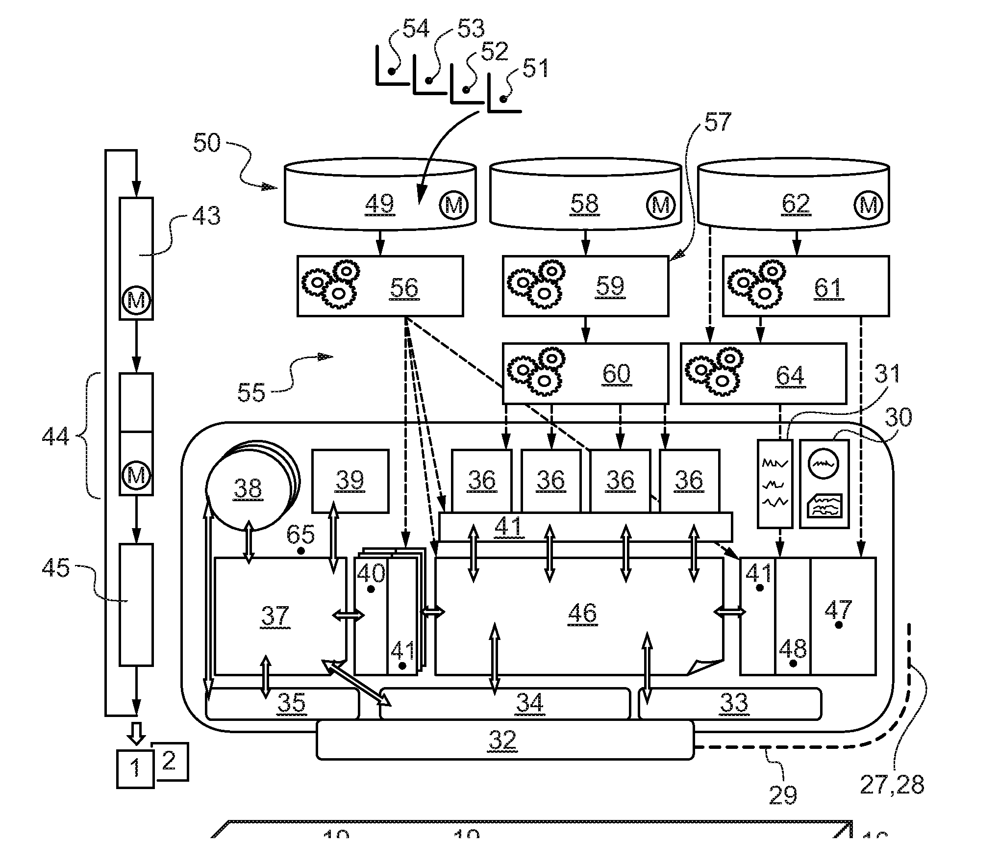
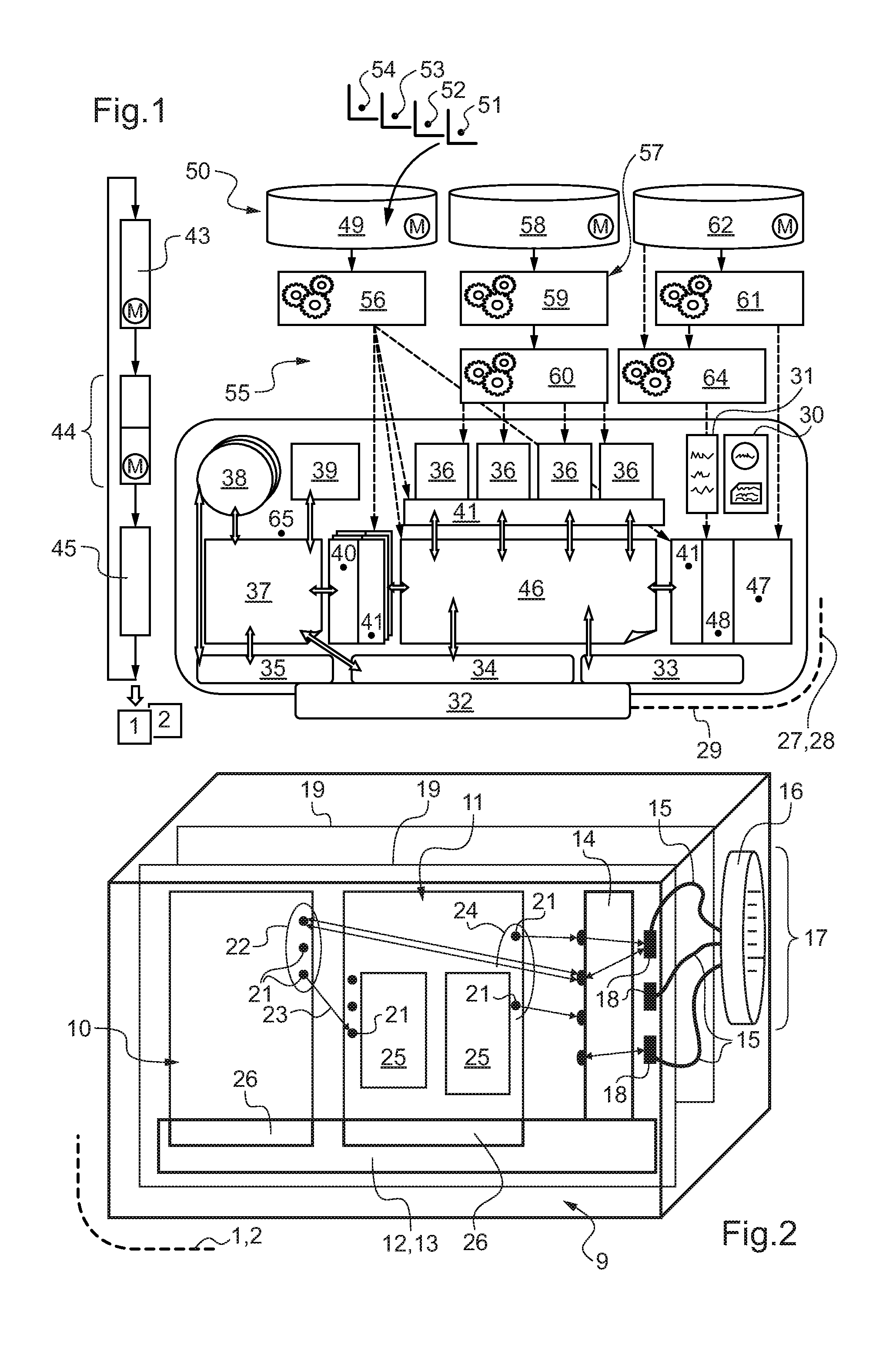
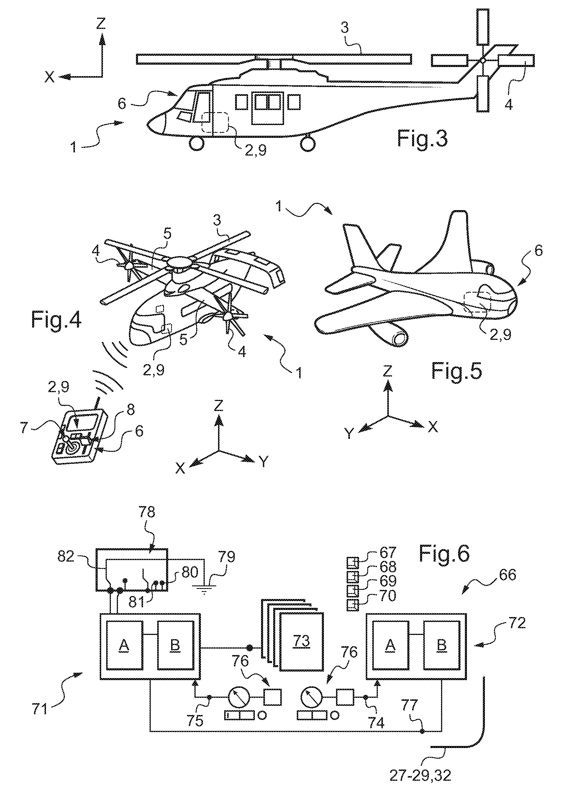
[0136]After FIGS. 1 and 2 (summarized above), in FIGS. 3 to 5 in particular, reference 1 is an overall reference to an aircraft. The aircraft 1 includes at least one avionics system 2 that has been subjected to simulation in accordance with the invention, as described below.

[0137]FIGS. 3 to 5 also show three mutually orthogonal directions X, Y, and Z. In aviation, the direction X generally corresponds to the roll axis of the aircraft 1.

[0138]Another direction Y is a transverse direction and corresponds to the widths or lateral dimensions of the structures described. The longitudinal direction X and the transverse direction Y are sometimes said to be horizontal, for simplification purposes.

[0139]A third direction Z referred to as the elevation direction corresponds to the height dimensions of the structures described. Sometimes the elevation direction Z is said to be vertical.

[0140]In FIG. 3, the aircraft 1 of...


PUM


Abstract

Optionally-mixed highly representative real time simulation of at least part of an avionics system (2). The simulation provides at least a step of translating communications interfaces into the form of models encoded in high level language on the basis of formal files in mark-up language; and dynamically managing descriptions that provide for grouping together, updating, and sharing a database that, for each piece of equipment, incorporates signals that transit via its input and / or output interfaces.

Description

CROSS REFERENCE TO RELATED APPLICATION [0001]This application claims the benefit of patent application no. FR 09 04545 dated Sep. 23, 2009, the disclosure of which is incorporated herein by reference.FIELD OF THE INVENTION [0002]The general field of the invention is aviation, i.e. aircraft, including airplanes and rotary wing aircraft, such as, but not limited to, conventional helicopters or hybrid helicopters and / or by drones of such aircraft.[0003]The specific field of the invention relates to aircraft avionics systems, and more particularly to simulating such systems. Such systems are also said to be “on-board” systems, even if nowadays some of their components may be situated elsewhere.[0004]The invention does not seek to produce simulations of so-called “mechanical” components of conventional aircraft. However such mechanical components may also include electrical or hydraulic components or may be involved in flight mechanics.[0005]Information representative of these components...

Claims


Application Information

Patent Timeline
Patent Type & Authority Applications(United States)
IPC IPC(8): G05D1/00G06F17/50
CPCG06F8/30G06F17/5095G06F8/44G06F30/15
Inventor DAMIANI, NICOLASTOUATI, ROLANDBRISSET, NICOLAS
Owner EUROCOPTER
Why Eureka
Try Eureka