
Wedging retainer gasket construction

a technology of retainer and gasket, which is applied in the field of sealing construction, can solve the problems of increased corrosion potential and loss of service li

Inactive Publication Date: 2011-03-31
KAMIBAYASHIYAMA JULIAN F
View PDF68 Cites 11 Cited by
  • Summary
  • Abstract
  • Description
  • Claims
  • Application Information

AI Technical Summary

Benefits of technology

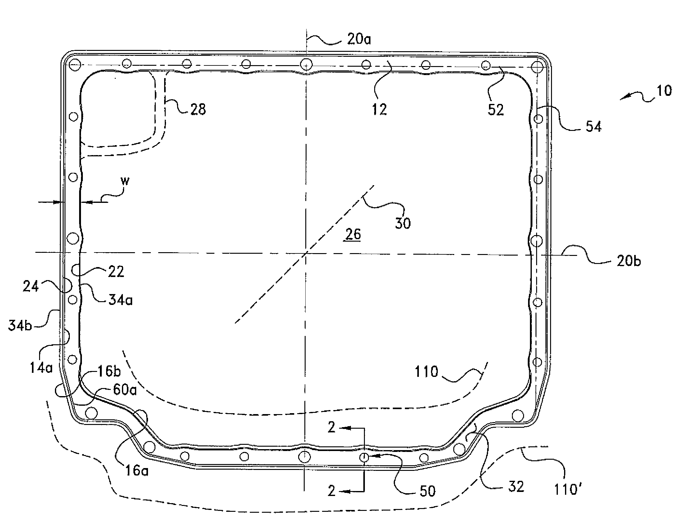
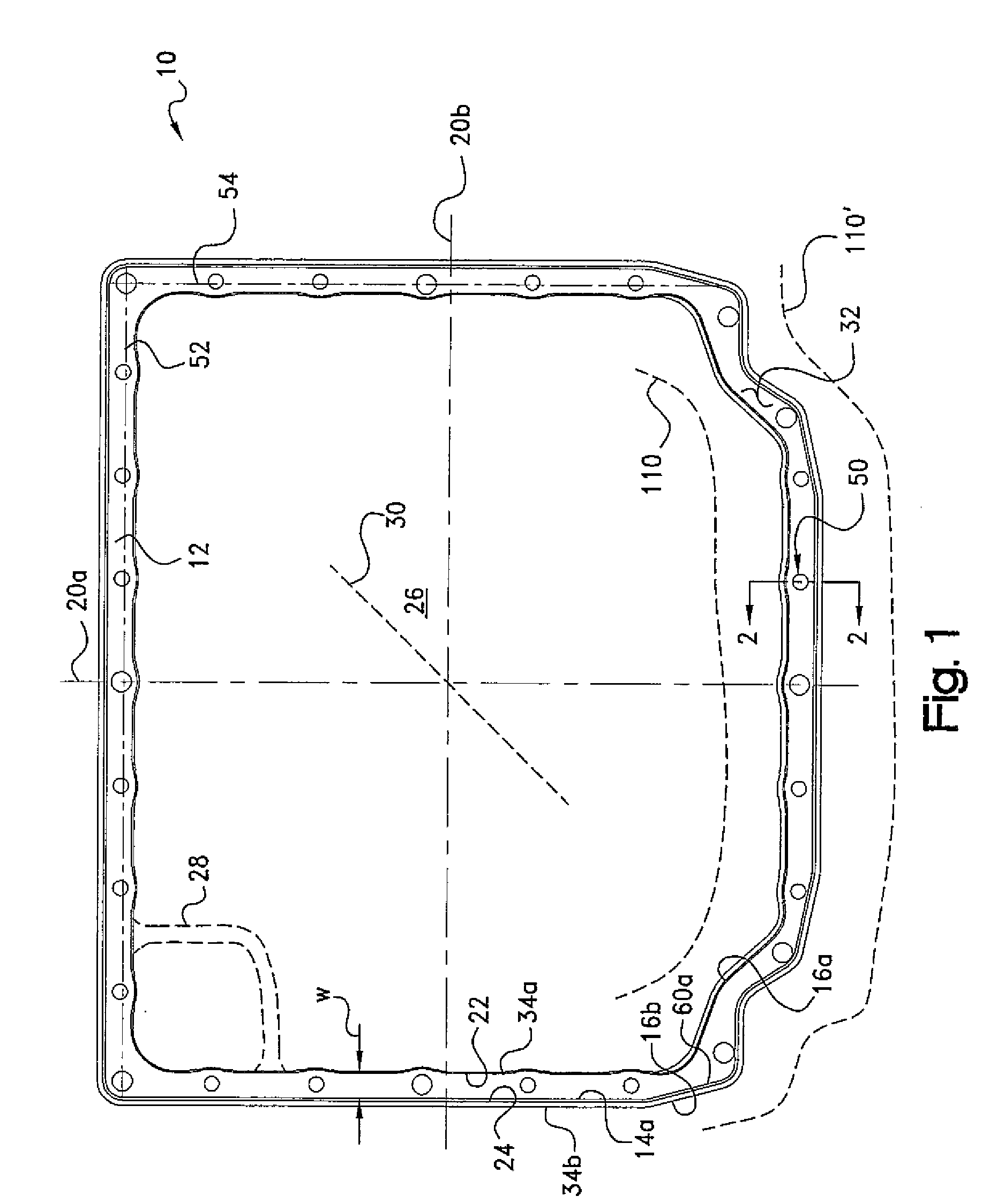
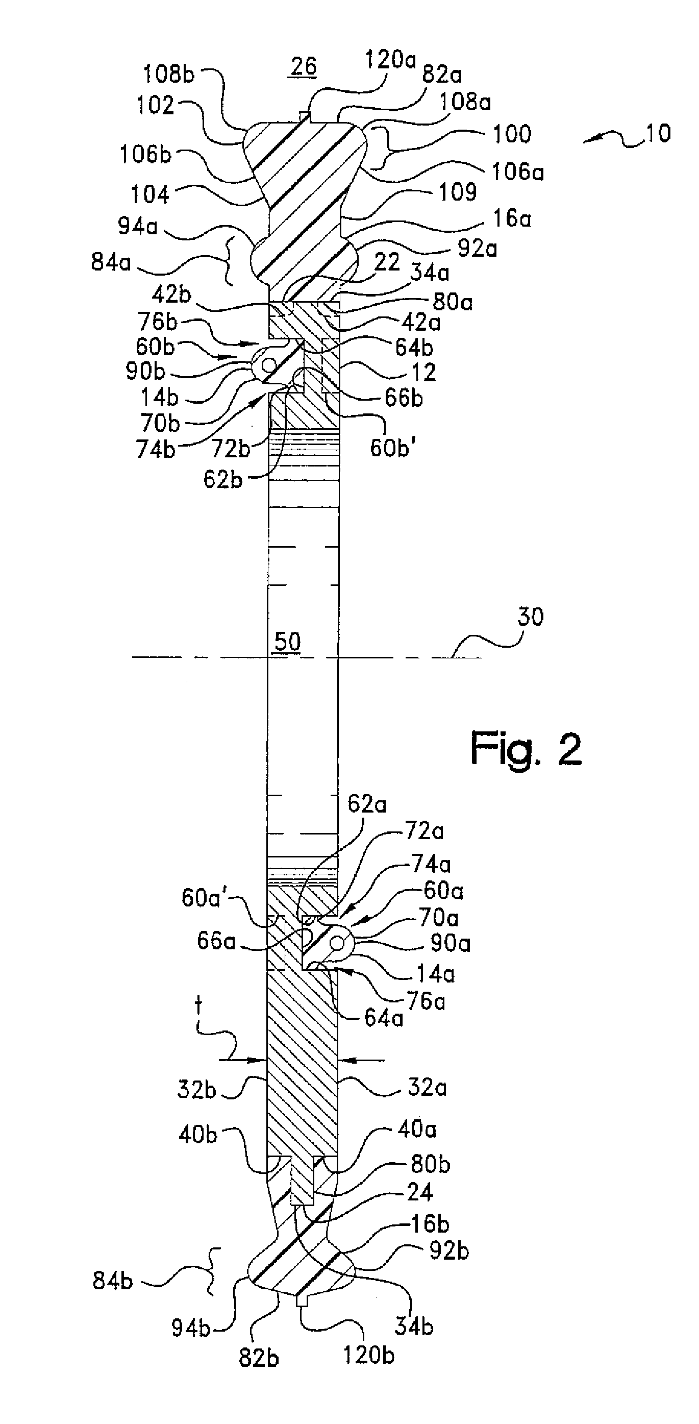
[0007]When the gasket is placed between the interfacing surfaces to be sealed, with at least one of those surfaces having an edge confronting one of the sides of the gasket, the wedge-shaped sealing element thereof is positioned to extend into a void space defined along that edge. Such space may be formed, for example, by a radius or chamfer extending between the edge and the face of the corresponding one of the interfacing surfaces. In this regard, when the gasket thereupon is compressed between the interfacing surfaces, the wedge shape of the sealing element assists in filling with seal material the void space that otherwise would be formed at the radiused edged of the one of the surfaces. In so filling such space, the gasket of the present invention advantageously eliminates an area in which fluid otherwise could collect. Such collection can result in increased potential for corrosion and a loss of service life.

Problems solved by technology

Such collection can result in increased potential for corrosion and a loss of service life.

Method used


Image

  • Wedging retainer gasket construction
  • Wedging retainer gasket construction
  • Wedging retainer gasket construction

Examples


Embodiment Construction

[0017]Certain terminology may be employed in the following description for convenience rather than for any limiting purpose. For example, the terms “forward” and “rearward,”“front” and “rear,”“right” and “left,”“upper” and “lower,”“top” and “bottom,” and “right” and “left” designate directions in the drawings to which reference is made, with the terms “inward,”“inner,”“interior,”“inside,” or “inboard” and “outward,”“outer,”“exterior,”“outside,” or “outboard” referring, respectively, to directions toward and away from the center of the referenced element, the terms “radial” or “vertical” and “axial” or “horizontal” referring, respectively, to directions, axes, or planes perpendicular and parallel to the longitudinal central axis of the referenced element. Terminology of similar import other than the words specifically mentioned above likewise is to be considered as being used for purposes of convenience rather than in any limiting sense.

[0018]In the figures, elements having an alphan...


PUM

PropertyMeasurementUnit
Elastomericaaaaaaaaaa
Radiusaaaaaaaaaa
Areaaaaaaaaaaa

Abstract

Sealing gasket construction for providing a fluid seal intermediate a pair of opposed, mating parts or structures, one of the parts having an edge and a void space defined along the edge. The gasket includes a retainer and a resilient seal element having a wedging portion extending radially beyond one of the retainer inner or outer perimeter. The wedging portion is configured in a free state to extend into the area of the void space and to be wedged against the other one of the interfacing parts, and thereby made to occupy at least a portion of the void space.

Description

CROSS REFERENCE TO RELATED CASES[0001]This application is a divisional of U.S. patent application Ser. No. 11 / 102,262, filed Apr. 8, 2005, which claims priority to U.S. Provisional Application Ser. No. 60 / 603 / 726; filed Aug. 23, 2004, the disclosures of which are expressly incorporated herein by reference.BACKGROUND OF THE INVENTION[0002]The present invention relates broadly to a sealing construction for providing a fluid seal intermediate a pair of opposed, mating parts or structures, and more particularly to such a construction including a wedge-shaped seal member which is adapted to fill a void volume created by a radiused edge of one of the mating parts so as to prevent fluid accumulation in such volume.[0003]In basic construction, gaskets of the type herein involved are formed of one or more resilient sealing elements which are supported by sheet metal plate or other retainer which may be machined, stamped, molded or otherwise formed to conform to the geometry of the mating sur...

Claims


Application Information

Patent Timeline
IPC IPC(8): B23P17/04
CPCF16J15/061F16J15/064Y10T29/49863F16J15/127F16J15/123
Inventor KAMIBAYASHIYAMA, JULIAN F.
Owner KAMIBAYASHIYAMA JULIAN F
Learn More