Pneumatic tire

a technology of pneumatic tires and tires, applied in the field of pneumatic tires, can solve the problems of adverse effects, water remains in the tire housing, and water pushed backwards, and achieve the effects of sufficient hydroplaning prevention performance, suitable running performance, and reduced water pushed backwards

Active Publication Date: 2011-03-31
YOKOHAMA RUBBER CO LTD
View PDF8 Cites 15 Cited by
  • Summary
  • Abstract
  • Description
  • Claims
  • Application Information

AI Technical Summary

Benefits of technology

[0007]According to the present invention, a center main groove and subsidiary main grooves extending in the tire circumferential direction are provided in the center area of the tread portion, while a plurality of angled grooves and a plurality of lateral grooves are provided extending at an angle in a direction opposite the rotational direction towards the outside in the tire width direction, and furthermore, a plurality of sub grooves extending from each lateral groove towards the rotational direction is provided. Therefore, when traveling on a wet road surface, water on the road surface is drained towards the tire width direction and thus the amount of water pushed back forwards can be reduced. It is thus possible to guarantee sufficient hydroplaning prevention performance when traveling straight. Also, in races with GT touring cars having tire housings, water can be prevented from remaining in the tire housings.
[0008]Furthermore, there is a tendency for suitable running performance to be easily exhibited on wet road surfaces for a tire wherein the center area of the tread portion has a contact pressure (surface pressure) of a certain degree even when the load applied to the tire fluctuates. By making the number of grooves in the center area relatively large, a road surface contact pressure per unit area increases, thus making improvement in running performance on wet road surfaces possible. However, increasing an area of the grooves alone leads to a deterioration of block rigidity in the center area, and since desired running performance cannot thus be achieved, the total length of the block edge in the center area is defined as disclosed above. It is thus possible to improve running performance on wet road surfaces effectively.
[0009]Also, since the end on the leading side of the sub grooves formed in each block between the lateral grooves is closed, and the blocks on the shoulder sides are not further divided by these sub grooves, sufficient rigidity of the tread portion can be guaranteed. It is therefore possible to achieve superior braking performance and turning performance on wet road surfaces. Running performance on wet road surfaces when traveling straight and when cornering can thus be improved beyond that which was conventionally possible.
[0010]In the present invention, the lateral grooves are preferably curved so that the inclination angle to the tire circumferential direction increases towards the outside in the width direction. Drainage performance based on the lateral grooves can thus be improved.
[0011]Preferably, the width of each sub groove is 3 mm or more and the length in the tire circumferential direction of each sub groove is 50% or more of the length in the tire circumferential direction of each corresponding block. Also, the inclination angle of each sub groove to the tire circumferential direction is preferably 15° or less. Drainage performance based on the sub grooves can thus be improved.
[0012]A distance W2 between the terminal center position of the leading side of adjacent sub grooves in the tire width direction with respect to a distance W1 between the center position of the subsidiary main grooves and the terminal center position of the leading side of the sub groove positioned nearest on a tire equatorial line side in the tire width direction preferably satisfies the relationship 0.85≦W2 / W1≦1.15. By thus disposing the sub grooves at approximately equal distances, water on a road surface can be drawn effectively into the sub grooves. Each of the above-mentioned distances is a distance measured in the tire width direction along the tire tread surface.

Problems solved by technology

However, in high speed races, an amount of water pushed ahead increases since water cannot be drained by the main grooves in tires having a tread pattern with main grooves extending in the tire circumferential direction as a main constituent, which results in an occurrence of a hydroplaning phenomenon.
Also, in races with Gran Turismo (GT) touring cars having tire housings, there is an adverse effect whereby water remains in tire housings when tires having a tread pattern with main grooves extending in the tire circumferential direction as the main constituent are used.
However, when the tread portion is partitioned into a plurality of blocks by the main groove and the angled grooves as disclosed above, a rigidity of the tread portion deteriorates.
Since a large load is applied to tires when braking and when cornering in racing, there is a problem that a necessary braking performance and cornering performance on wet road surfaces cannot be exhibited when the rigidity of the tread portion is insufficient.

Method used


Image

  • Pneumatic tire
  • Pneumatic tire
  • Pneumatic tire

Examples


examples

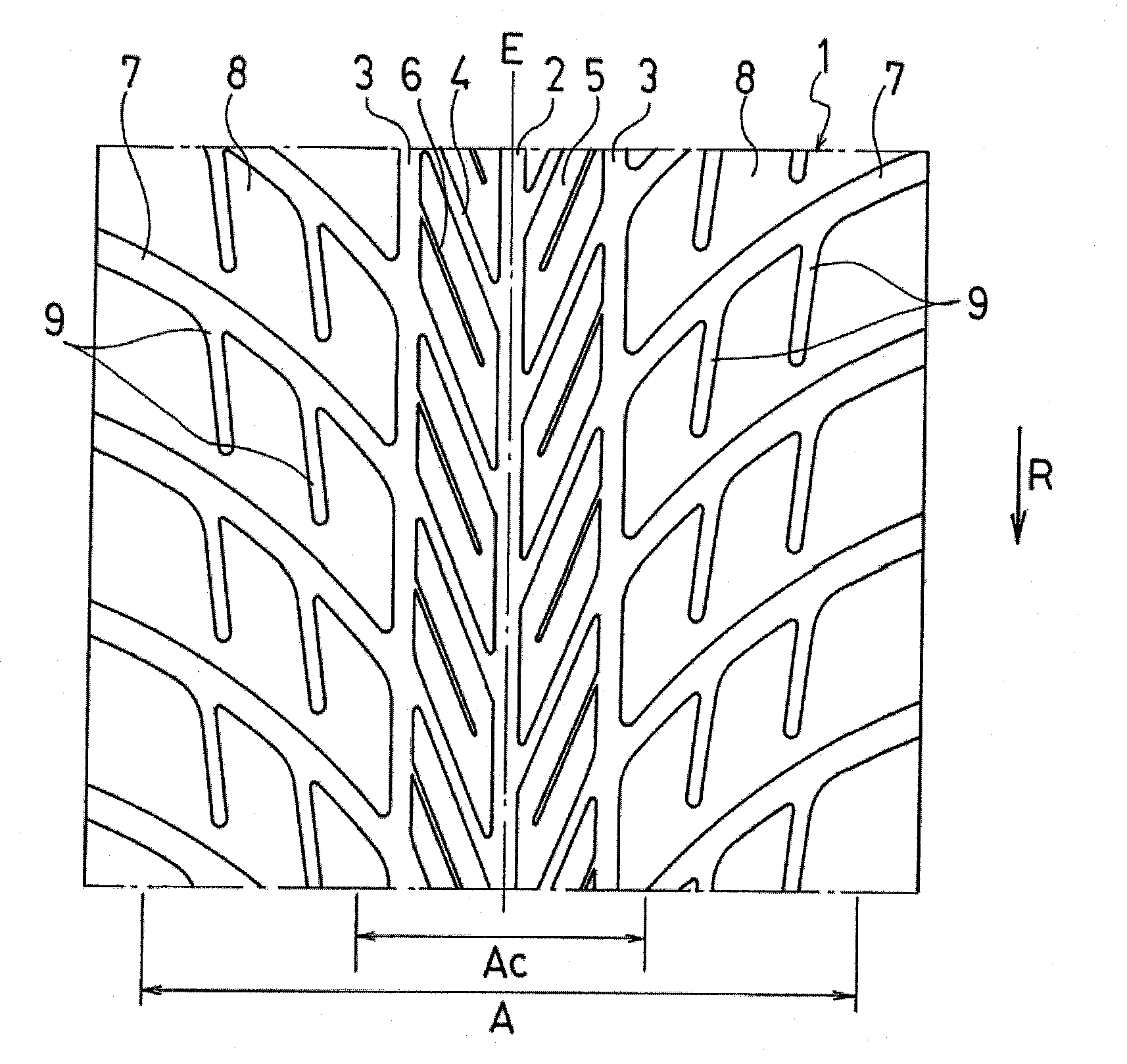
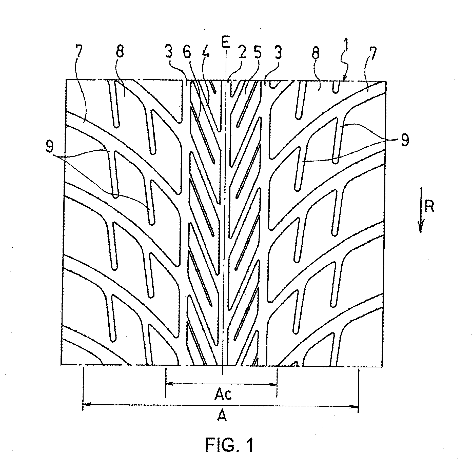
[0036]Tires having a designated rotational direction and different tread patterns were prepared for a conventional example, Examples 1 to 3, and Comparative Examples 1 to 4. The tire size was 280 / 710R18.

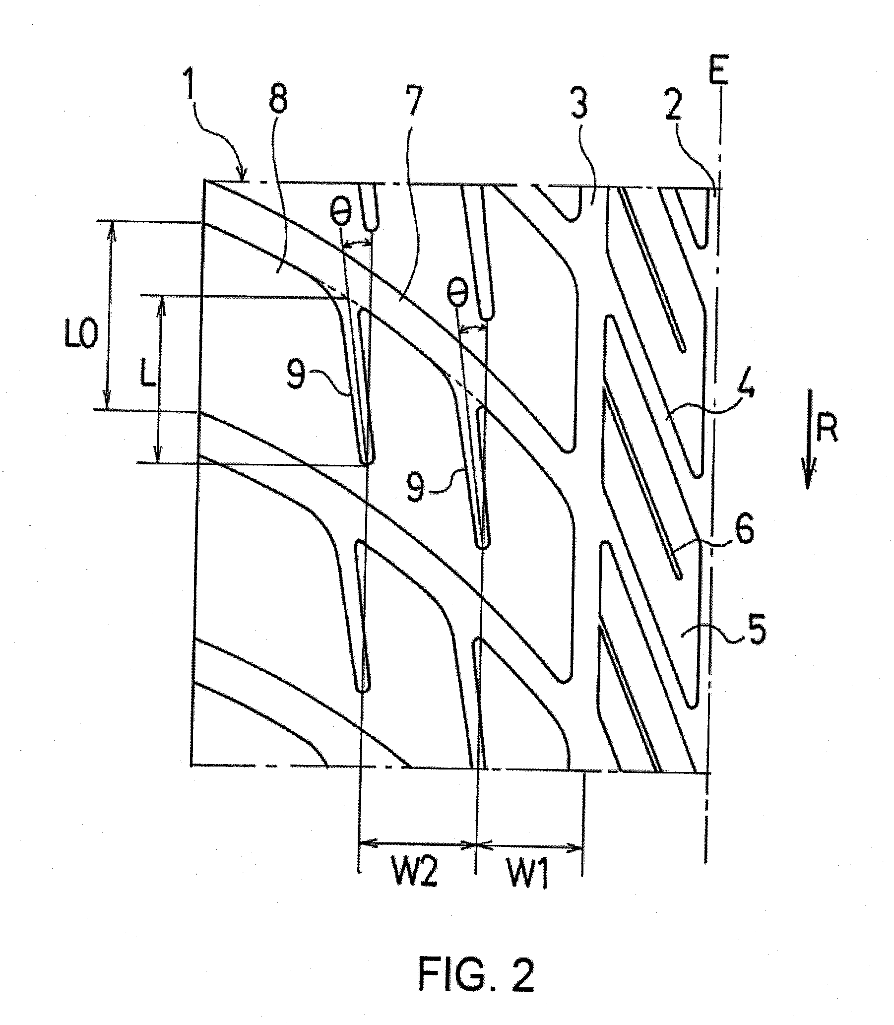
[0037]As shown in FIG. 1, the tires of Examples 1 to 3 are tires wherein, when an entire area having a width 85% of the total tire width and a center area having a width 30% of the total tire width are defined in the tread portion, one center main groove and two subsidiary main grooves extending in the tire circumferential direction are provided in the center area; a plurality of angled grooves that extend at an angle, in a direction opposite the rotational direction, towards the outside in the tire width direction are provided between the center main grooves and the subsidiary main grooves; sipes extending along the angled grooves from the respective subsidiary main grooves are provided in each block partitioned by the angled grooves and the end on the tire equatorial line side of t...


PUM


Abstract

A pneumatic tire having a designated rotational direction is disclosed, wherein an entire area having a width 85% of a total tire width and a center area having a width 30% of the total tire width are defined in a tread portion. A center main groove is positioned on a tire equatorial line and extends in a tire circumferential direction. Subsidiary main grooves are positioned on two sides of the center main groove and extend in the tire circumferential direction. Angled and lateral grooves extend at an angle, in a direction opposite the rotational direction towards an outside in the tire width direction. Lateral grooves extend from each subsidiary main groove. Sub grooves extend from the lateral grooves towards the rotational direction. A total length of a block edge in the center area is from 40% to 60% of a total length of a block edge in the entire area.

Description

PRIORITY CLAIM[0001]This application is based upon and claims the benefit of priority from Japanese Patent Application No. 2009-63085, filed Mar. 16, 2009, the entire contents of which are incorporated herein by reference.TECHNICAL FIELD[0002]The present invention relates to a pneumatic tire suitable as a racing tire, and in particular relates to a pneumatic tire that can improve running performance on a wet road surface when traveling straight and when cornering.BACKGROUND ART[0003]Tires provided with a plurality of main grooves extending in a tire circumferential direction in a tread portion are normally used as wet tires for racing. It is recognized that superior running performance of such tires on wet road surfaces are exhibited based on a drainage capability of the main grooves. However, in high speed races, an amount of water pushed ahead increases since water cannot be drained by the main grooves in tires having a tread pattern with main grooves extending in the tire circumf...

Claims


Application Information

Patent Timeline
Patent Type & Authority Applications(United States)
IPC IPC(8): B60C11/12
CPCB60C11/0302B60C11/12B60C2011/0374B60C2011/0381Y10S152/03B60C2011/1209
Inventor ISHIGURO, SADAYUKIENDOU, KENICHIROU
Owner YOKOHAMA RUBBER CO LTD
Why Eureka
Try Eureka