
Sampling Device

Active Publication Date: 2011-04-07
INFORS
View PDF8 Cites 5 Cited by
  • Summary
  • Abstract
  • Description
  • Claims
  • Application Information

AI Technical Summary

Benefits of technology

[0006]It is therefore the object of the invention to provide an improved sampling device which is less problematic regarding function and effectiveness.
[0011]Thus, in a surprisingly simple manner, the new sampling device according to the invention enables aseptic sample collection in a very simple fashion. It offers the possibility to replace the culture solution in the device by sterile air after the sampling, whereby it is no longer necessary to subsequently rinse the sampling device and reject or discharge the culture solution as has been necessary in the past. This is of great importance, particularly for small culture vessels in which the culture volume remaining in the culture vessel could be reduced below a critical value due to the sampling.
[0012]Operating errors are also constructively excluded because the flow directions are clearly defined by the check valves. Thus, an accidental contamination of the culture vessel via the sampling is not possible either. It is even possible to carry out a sterile further processing of the samples. The dead volume may be reduced to less than 0.1 ml, which represents a negligibly small value. It also is a great advantage that the system can be autoclaved several times.
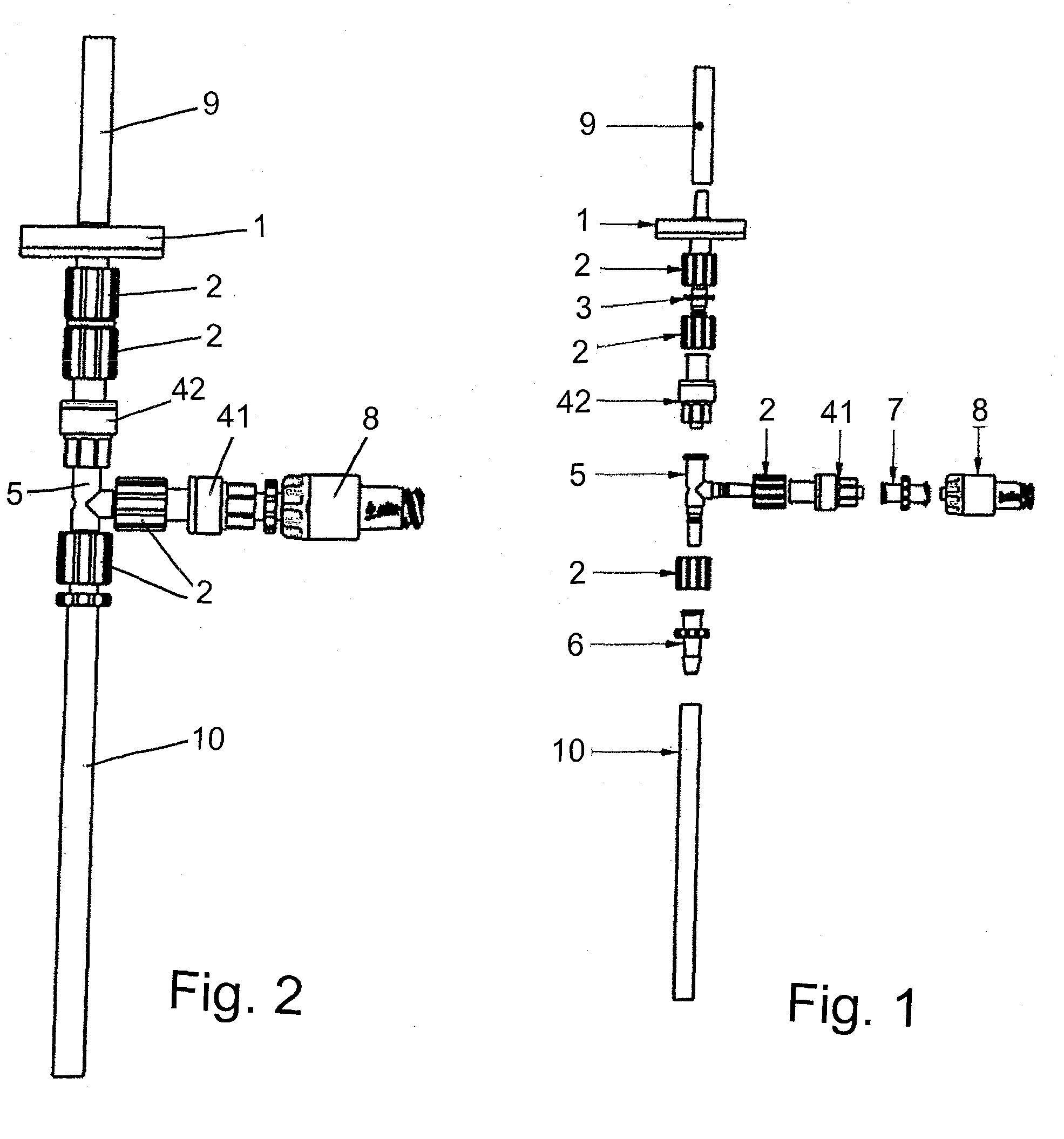
[0014]It is a particular advantage that in the inventive device the sterile syringe comprising the Luer Lock taper, the second syringe, the automatic valve, the T piece, the stub, the first check valve, the second check valve, the piece of tube, the air filter and / or the connecting tube as a system may consist of known, commercially available components that can be combined with one another and are delivered as a set, optionally assembled in part, so that they can be assembled to form the device in a very unproblematic, inexpensive and easy manner.

Problems solved by technology

According to the teaching of the invention, due to the first check valve it is possible to collect a sample via the connection by using the sterile syringe, but it is not possible, however, to introduce fluids in the reverse flow direction.
Finally, the inventive device merely allows the introduction of air via a preferably provided sterile filter, but does not allow the withdrawal of the culture solution, which would damage the sterile filter.
Therefore, according to the teaching of the invention, sampling by using the sterile syringe is possible via the through conduit, however, the supply of fluids in the reverse flow direction is not possible due to the two check valves.

Method used


Image

  • Sampling Device
  • Sampling Device

Examples


Embodiment Construction

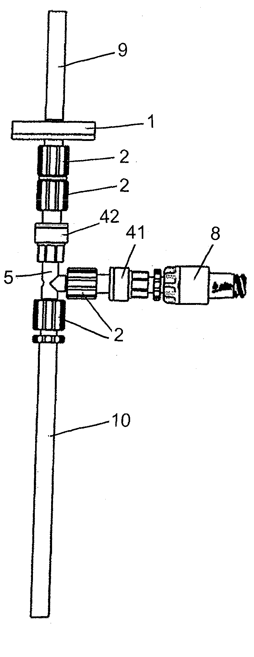
[0019]The device shown in FIG. 1 serves to sample cultures such as microorganisms or cells via a connection 10 formed as a connecting tube leading from one or more autoclavable culture vessels (not shown) by using a sterile syringe for receiving the actual sample and having a so-called Lock Luer taper via an automatic valve 8 that automatically opens when the syringe is attached and automatically closes when the syringe is detached.

[0020]Between the automatic valve 8 and the connection 10, a T piece 5 is disposed that connects the latter via a through conduit and comprises a stub having an air filter 1. At the end of the stub a second syringe can be connected via a piece of tube 9. A first check valve 41 closing towards the T piece 5 is provided in the through conduit, and a second check valve 42 opening towards the T piece is disposed in the stub.

[0021]In the device according to the invention, preferably the sterile syringe comprising the Luer Lock taper, the second syringe, the au...


PUM


Abstract

A device for sampling cultures such as microorganisms or cells via a connection (10) from autoclavable culture vessels, including a sterile syringe for receiving the sample and having a so-called Luer Lock taper and an automatic valve (8) that automatically opens when the syringe is attached and automatically closes when the syringe is detached, and further including a first check valve (41) closing towards the automatic valve (8) and provided between the automatic valve (8) and the connection (10).

Description

CROSS REFERENCE TO RELATED APPLICATIONS[0001]This application claims priority from Federal Republic of Germany patent application no. DE 10 2009 043 699.5, filed Oct. 1, 2009, the entire disclosure of which is incorporated herein by reference.BACKGROUND OF THE INVENTION[0002]The present invention relates to a generic device for taking a sample, that is, a device for sampling culture solutions such as microorganisms (e. g. bacteria, yeasts, fungi) or cells (e. g. mammal and insect cells) via a connecting tube from preferably autoclavable culture vessels such as bioreactors or disposable cultivation systems such as plastic bags or pouches for cultivating microorganisms or cells using a sterile syringe receiving the sample and having a so-called Luer Lock taper and an automatic valve that automatically opens when the syringe is attached and automatically closes when the syringe is detached, also referred to as an injection site.[0003]Cultivations of bacteria, yeasts, fungi and animal c...

Claims


Application Information

Patent Timeline
IPC IPC(8): G01N1/12
CPCC12M33/04G01N2001/1418G01N2001/1427
Inventor BRUECHER, DANIEL
Owner INFORS
Learn More