Overcurrent protection device having free trip mechanism

a protection device and free trip technology, applied in the direction of protective switch details, contact mechanisms, relays, etc., to achieve the effect of reducing the risk of overcurrent protection devices

Inactive Publication Date: 2011-04-07
CHEN TSAN CHI
View PDF34 Cites 5 Cited by
  • Summary
  • Abstract
  • Description
  • Claims
  • Application Information

AI Technical Summary

Benefits of technology

[0009]An object of the present invention is to provide an overcurrent protection device having a free trip mechanism. The overcurrent protection device comprises a housing, an elastic element, a memory alloy plate and an elastic metal sheet, wherein the housing has a first side mounted with a first wire terminal and a second wire terminal, and a second side having an opening installed with a button. The button has a lower surface provided with an extended rod on which the elastic element is sleeved. The elastic element has a first end abutting against the lower surface of the button, and a second end abutting against a stopping block formed on an inner side wall of the housing. The memory alloy plate is disposed in the housing, and has a first end connected to the first wire terminal and a free end having a first contact which is aligned with the extended rod, while the second wire terminal has a second contact aligned with the first contact. The elastic metal sheet has a first end movably connected to a position of the memory alloy plate close to the first end thereof, and a second end movably connected to an end edge of the free end of the memory alloy plate. When the button is pressed, the extended rod can push the first contact, so that the free end is shifted to overcome a critical deformation stress of the free end for triggering the free end to deform. Thus, the first contact can contact the second contact, and the first wire terminal will be electrically connected to the second wire terminal. At this time, because the elastic element is compressed between the button and the stopping block, an elastic force accumulated by the compression of the elastic element will be released when the button is released. Thus, the button will be shifted away from the first contact to provide a space for the free end to return an original status prior to deformation of the memory alloy plate. When the temperature of the memory alloy plate is over a predetermined temperature due to the overload of the current passing through the memory alloy plate, the free end will return to the un-deformation status due to the thermal memory effect, so that the first contact will be separated from the second contact to form an open mode. As a result, such configuration efficiently prevents the accident caused by the problem that the overcurrent protection device is overheated and the first contact can not be separated from the second contact. Therefore, the safety of the overcurrent protection device can be substantially enhanced, while the related manufacturers can fabricate highly safe overcurrent protection devices with lower design costs.

Problems solved by technology

(1) When the current is suddenly raised to increase the temperature of the memory alloy plate 14 and deform the memory alloy plate 14 to separate the first contact 16 and the second contact 17, the blocking plate 110 must return to be sandwiched between the first contact 16 and the second contact 17, in order to efficiently prevent the overcurrent protection device 1, wires and related appliances connected thereto from repeatedly receiving the overcurrent over the predetermined loading value. However, because the separation distance of the first contact 16 and the second contact 17 is deformed according to the influence of the temperature of the memory alloy plate 14, the thickness design of the blocking plate 110 for separating the first contact 16 from the second contact 17 is important. If the blocking plate 110 is excessively thick, the blocking plate 110 may not smoothly return to be sandwiched between the first contact 16 and the second contact 17 due to excessively small separation distance of the first contact 16 and the second contact 17 when the current is suddenly raised to heat and deform the memory alloy plate 14 to separate the first contact 16 and the second contact 17, resulting in causing the overcurrent protection device 1, wires and related appliances connected thereto to repeatedly receive the overcurrent over the predetermined loading value. In addition, if the blocking plate 110 is excessively thin, the blocking plate 110 may be easily broken, resulting in losing the protection function of the overcurrent protection device 1. As a result, the overcurrent protection device 1 can not smoothly finish the protection measure of power interruption when the current is overloaded.
(2) When the current is suddenly raised, there are still some risks which may cause that the first contact 16 and the second contact 17 can not smoothly separate from each other. For example, when foreign objects are carelessly placed on the button 11 or when the gap between the button 11 and the housing 10 is filled with dirt over years, the button 11 may difficultly be moved. As a result, the button 11 can not be smoothly moved upward based on the elastic force of the spring 15 for returning the blocking plate 110 to be sandwiched between the first contact 16 and the second contact 17. Therefore, when the current is overloaded under a contact status of the first contact 16 and the second contact 17, the temperature of the memory alloy plate 14 will be raised, and the memory alloy plate 14 will deform to separate the first contact 16 from the second contact 17. Then, after the temperature of the memory alloy plate 14 is lowered under the separation status of the first contact 16 and the second contact 17, the first contact 16 and the second contact 17 will return to contact each other. As a result, not only do the overcurrent protection device 1, wires and related appliances connected thereto repeatedly receive the overcurrent over the predetermined loading value, but also some electric arc may occur between the first contact 16 and the second contact 17 due to the inexact insulation therebetween, resulting in damaging the overcurrent protection device 1, wires and related appliances connected thereto or causing fire accident due to arc sparking.

Method used


Image

  • Overcurrent protection device having free trip mechanism
  • Overcurrent protection device having free trip mechanism
  • Overcurrent protection device having free trip mechanism

Examples


Embodiment Construction

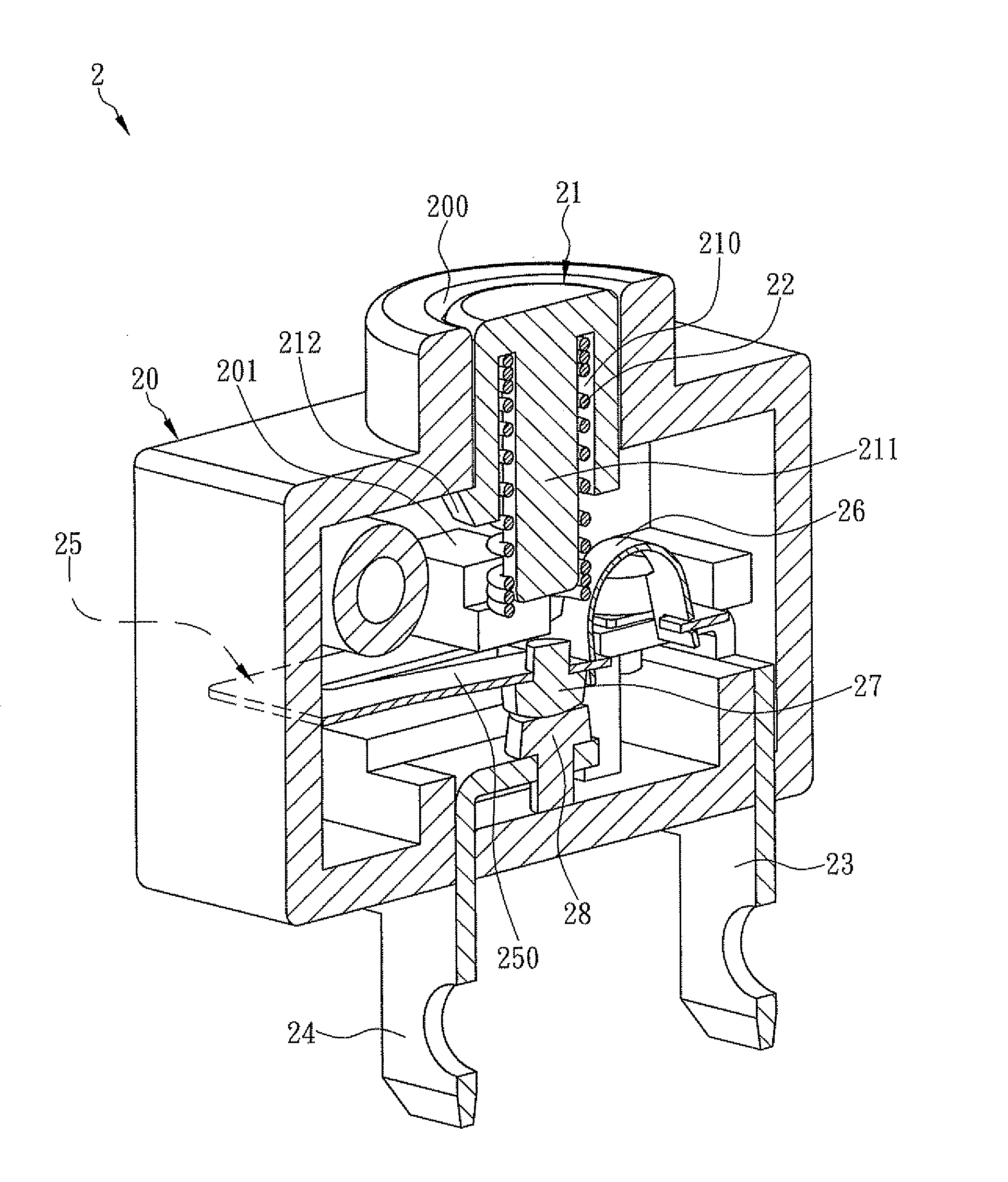
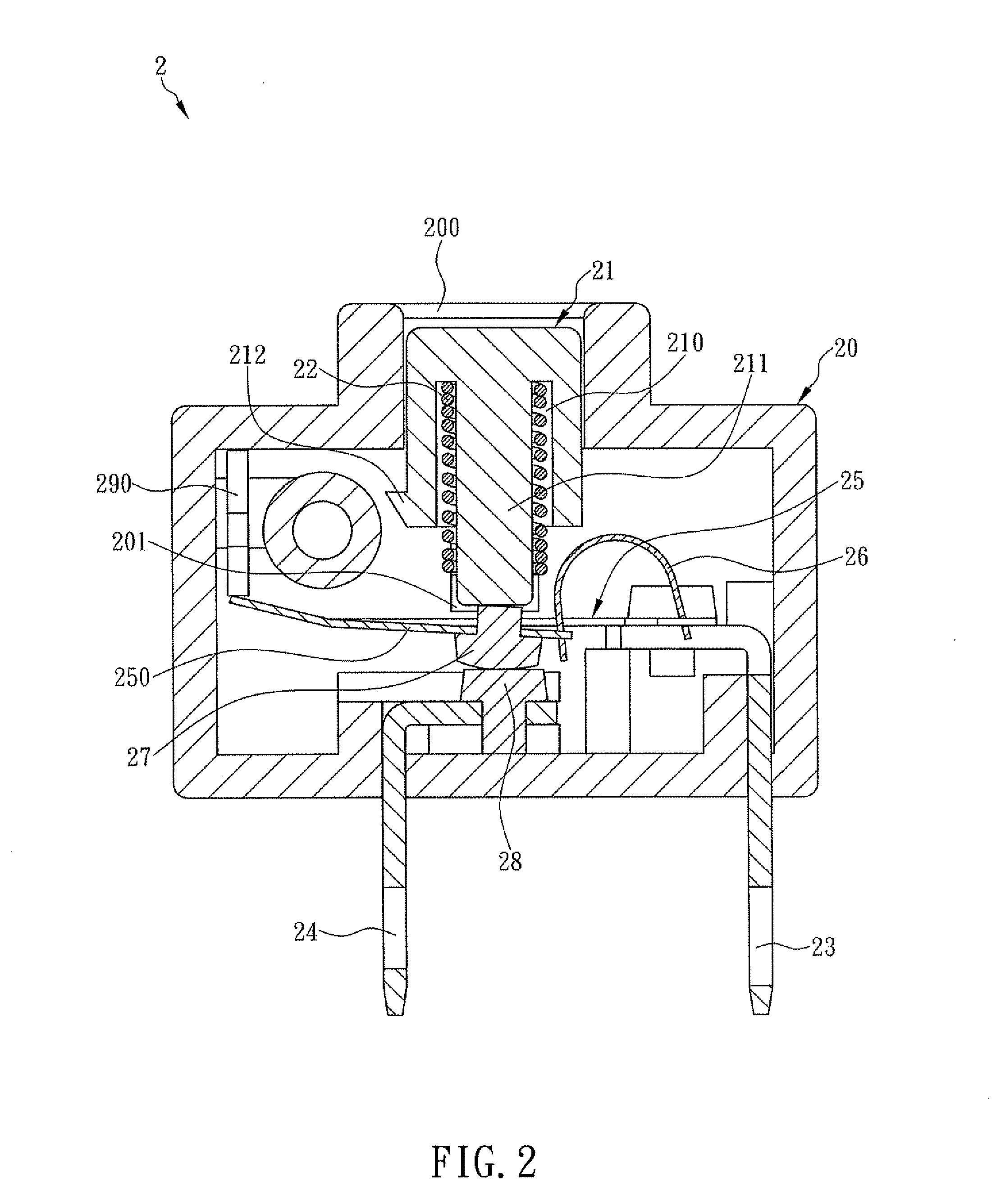
[0017]The present invention is an overcurrent protection device having a free trip mechanism. Referring now to FIG. 2, the overcurrent protection device 2 comprises a housing 20, a button 21, an elastic element 22, a first wire terminal 23, a second wire terminal 24, a memory alloy plate 25 and an elastic metal sheet 26, wherein the button 21 fits within an inner periphery of an opening 200 of the housing 20, and the button 21 has a lower surface formed with a receiving space 210 which receives therein an extended rod 211. The extended rod 211 has a first end connected to the lower surface of the button 21, while the length of the extended rod 211 is greater than that of a peripheral wall of the button 21. The elastic element 22 is sleeved on the extended rod 211. The elastic element 22 has a first end abutting against the lower surface of the button 21, and a second end abutting against a stopping block 201 formed on an inner side wall of the housing 20. The first wire terminal 23 ...


PUM


Abstract

This invention relates to an overcurrent protection device, which comprises a housing having a first side mounted with first and second wire terminals and a second side installed with a button, an elastic element installed therein for abutting against the button, a memory alloy plate disposed therein and having a first end connected to the first wire terminal and a free end having a first contact, and an elastic metal sheet having two ends movably connected to the first and free ends respectively. When the button is pressed, an extended rod thereof can push the first contact and cause the memory alloy plate to be deformed for enabling the first contact to contact a second contact on the second wire terminal. When the button is released and shifted away from the first contact, a space will be provided for the first contact to return an original status prior to deformation.

Description

FIELD OF THE INVENTION[0001]The present invention relates to an overcurrent protection device, more particularly to an overcurrent protection device having a free trip mechanism for preventing the overcurrent protection device from being overheated and avoiding contacts thereof from being unable to be separated with each other.BACKGROUND OF THE INVENTION[0002]Referring to FIG. 1, a traditional overcurrent protection device 1 is illustrated and comprises a housing 10, a button 11, a first wire terminal 12 and a second wire terminal 13, wherein the button 11 is disposed in a hole 100 of the housing 10. An upper surface of the button 11 is exposed out of the housing 10, while a lower side surface of the button 11 is extended to form a blocking plate 110 which is made of heatproof insulated bakelite material. A spring 15 is sandwiched between a lower end of the button 11 and an inner lower edge of the hole 100. Each of the first wire terminal 12 and the second wire terminal 13 is mounte...

Claims


Application Information

Patent Timeline
Patent Type & Authority Applications(United States)
IPC IPC(8): H01H71/10
CPCH01H73/30H01H71/16
Inventor CHEN, TSAN-CHI
Owner CHEN TSAN CHI
Why Eureka
Try Eureka