Instrumented handle and pedal systems for use in rehabilitation, exercise and training equipment

Active Publication Date: 2011-04-07
NORTHEASTERN UNIV
View PDF16 Cites 78 Cited by
  • Summary
  • Abstract
  • Description
  • Claims
  • Application Information

AI Technical Summary

Benefits of technology

[0010]The binding scheme can include front and rear binding ladder portions for releasably securing the user's foot to a foot plate, each portion securely and releasably attached to the foot plate, and front and rear binding pads for providing comfort to a dorsal side of the user's foot. Moreover, the binding scheme is structured and arranged so that a user's metatarsal-phalanges joint is immediately above or substantially immediately above an axis of rotation of the pedal.
[0011]Preferably, the velocity sensing device is a Hall effect sensing device that is mounted on the pedal raceway distant from the axis of rotati

Problems solved by technology

However, there are currently no modular systems that can adapt an existing, commercially-available, exercise device, such as a stationary or ex

Method used


Image

  • Instrumented handle and pedal systems for use in rehabilitation, exercise and training equipment
  • Instrumented handle and pedal systems for use in rehabilitation, exercise and training equipment
  • Instrumented handle and pedal systems for use in rehabilitation, exercise and training equipment

Examples


first embodiment

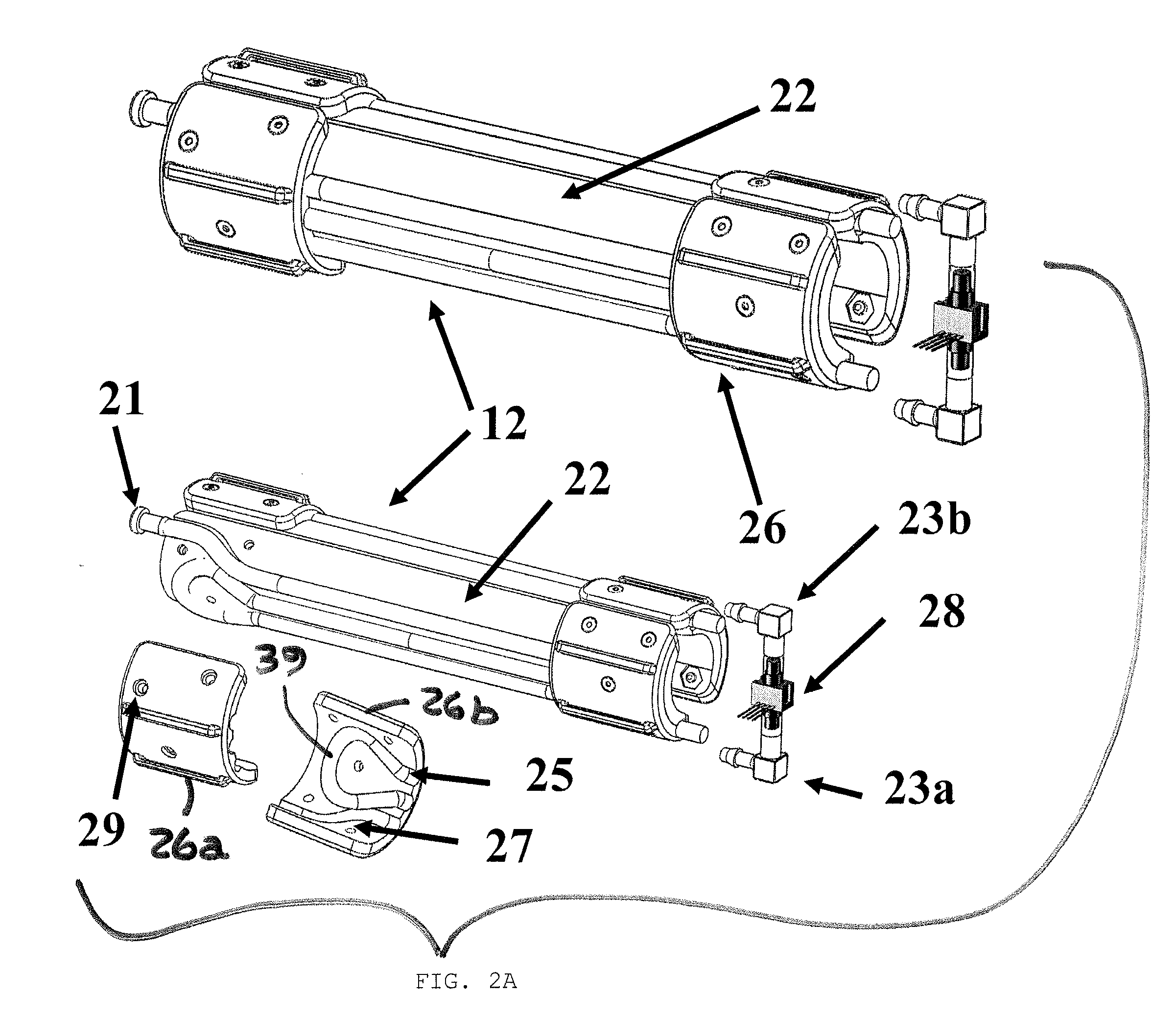
[0062]Similar to the handle bar housing 22 of the first embodiment, the base portion 77 is adapted to house hydraulic chambers 76 in a channel contour 25 and to be securely and releasably attached to the handle bar 79. The base portion 77 can be fabricated from a plastic or rubber material. To reduce the volume of material, a plurality of openings 75 can be provided in the base portion 77. At least two of the openings 75 in the base portion 77 are also used to provide a tight interference fit between a pair of alignment and fastening tabs 72 provided on the housing paddle 71 for attaching the latter to the former.

[0063]The paddle housing portion 71 can also be fabricated from a plastic or rubber material and is adapted to include the plurality of alignment and fastening tabs 72 for coupling the paddle housing portion 71 to the base portion 77 and channel contours 25 for confining the hydraulic chambers 76. The restraining cap 73 is structured and arranged to fit over the loop portio...

second embodiment

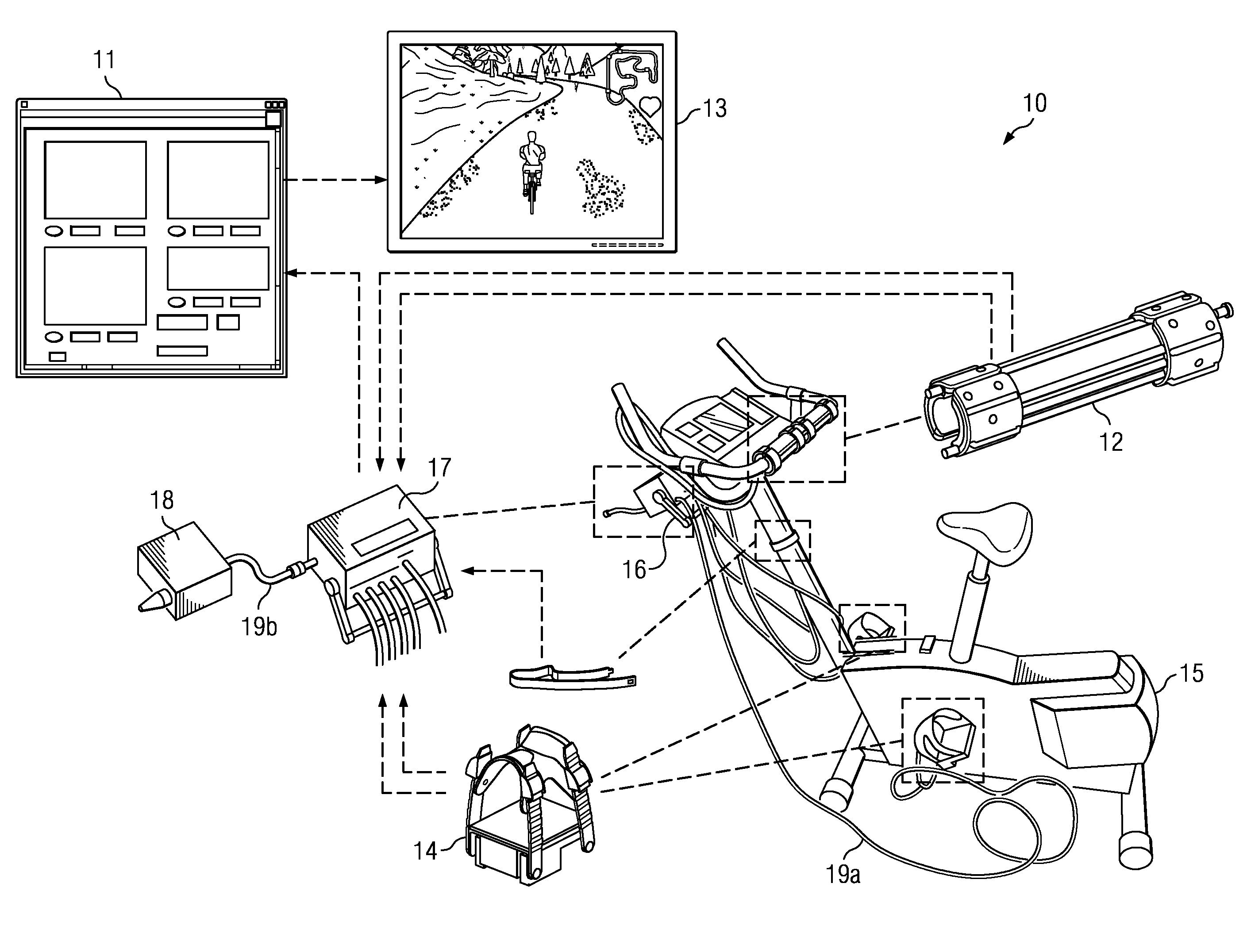
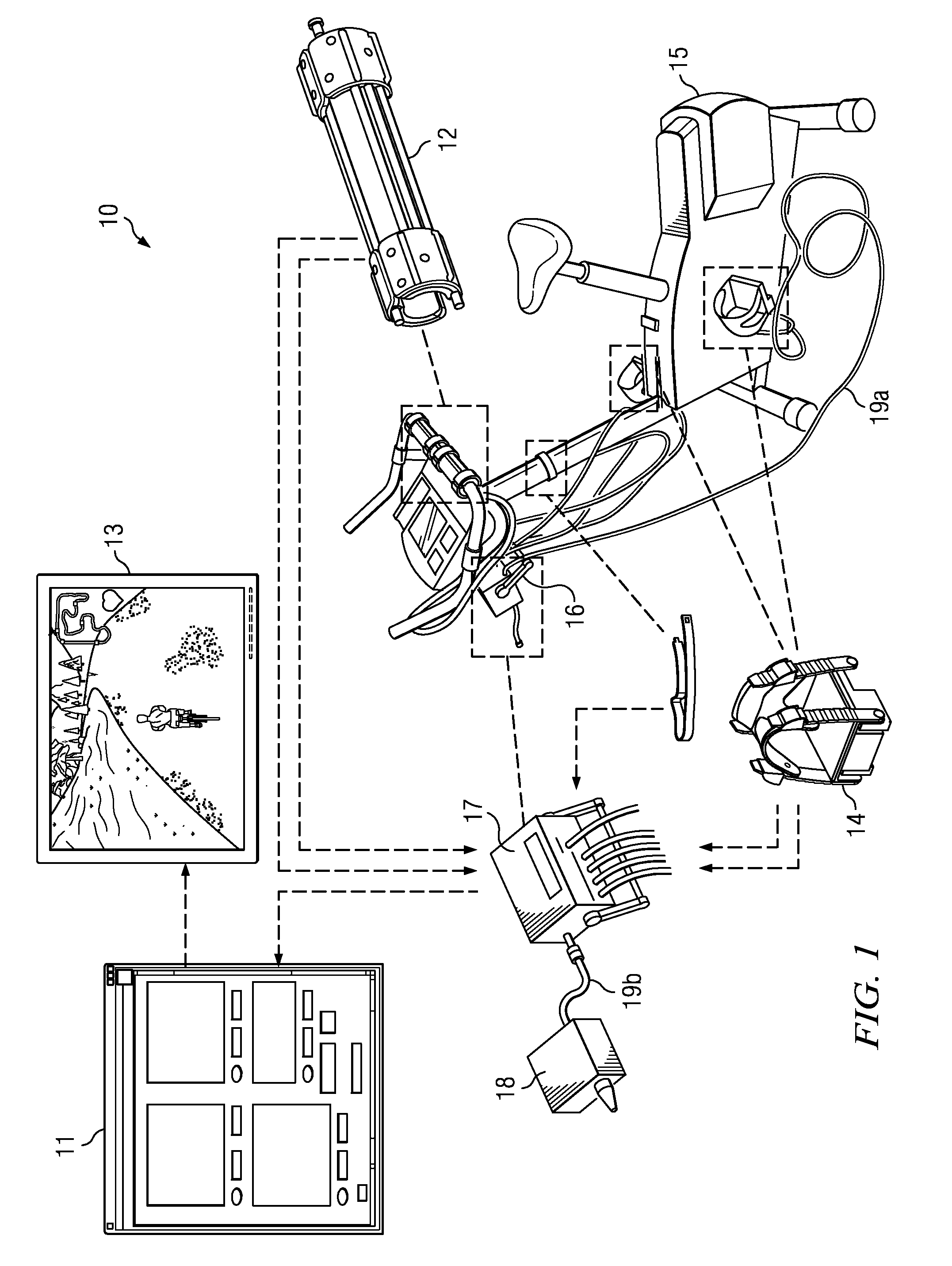
[0064]As described previously, first ends of the hydraulic chambers are fitted with a plug 78 while the other, second ends are fluidly coupled to pressure sensing devices 35, e.g., via elbow connections 33, which are enclosed in a protective hydraulic sensor enclosure 37. The pressure sensing devices 35 are adapted to generate parameter data signals, which can be transmitted to the signal box 17 via a shared electronics housing 74, e.g., via a multi-pin cable 30. Advantageously, the second embodiment disposes one sensor 35 on each of the front and rear sides of the handle bar module 12, doubling the number of sensors per module 12. In addition to enabling a practitioner to differentiate between a no load condition and a net zero force condition, having sensors 35 on the front and rear portions provides a better measure of turning forces.

[0065]Advantageously, handle bar modules 12 are inexpensive compared to alternatives having compression load cell. Moreover, the inherent elasticity...


PUM


Abstract

A mechatronic exercise system, e.g., for rehabilitation, having instrumented handle and pedal systems and, preferably, an interactive virtual environment is disclosed. Alternatively, the instrumented handle and pedal systems are part of a virtual reality augmenting kit that can convert most types of exercise equipment, such as a stationary or exercise bicycle, ergometer, rowing machine or the like, into full virtual reality (VR) smart systems. In another embodiment, the instrumented handle and pedal systems can each be used separately with other types of devices. In a preferred embodiment, components embedded with sensors are implemented, e.g., on a stationary, exercise bicycle to monitor physiological and biomechanical parameters of the user. Signal data from the sensing components is used to immerse the user in a VR simulation so as to provide the user with visual, auditory, and haptic feedback to the user's performance.

Description

CROSS-REFERENCE TO RELATED APPLICATIONS[0001]This application claims the benefit of U.S. Provisional Application No. 61 / 242,997, which was filed on Sep. 16, 2009.STATEMENT REGARDING FEDERALLY SPONSORED RESEARCH OR DEVELOPMENT[0002]This invention was made with government support under grant 1R13NS063655-01 awarded by the National Institutes of Health (NIH). The government has certain rights in the invention.BACKGROUND OF THE INVENTION[0003]Interest in coupling virtual environments with robotic devices and exercise equipment is high, which is, in part, based on findings that rehabilitative training on robotic devices that are augmented with virtual reality (VR) imaging has been shown to transfer to real world function better than training on robotic devices alone. These results are explained, in part, by the increased training intensity that a virtual environment provides. For example, stationary, exercise bicycles have been coupled with gaming applications in order to improve trainin...

Claims


Application Information

Patent Timeline
IPC IPC(8): A63B71/00
CPCA63B22/0605A63B2071/0652A63B24/0062A63B71/0622A63B2071/0644A63B2071/0655A63B2071/0691A63B2220/17A63B2220/30A63B2220/34A63B2220/51A63B2220/56A63B2220/58A63B2220/78A63B2230/06A63B23/16B33Y80/00
Inventor RANKY, RICHARDSIVAK, MARKLEWIS, JEFFREYDEUTSCH, JUDITHWEINBERG, BRIANMAVROIDIS, CONSTANTINOS
Owner NORTHEASTERN UNIV
Why Eureka
Try Eureka