Staged Multi-Tube Premixing Injector

a fuel injector and multi-tube technology, applied in the direction of machines/engines, combustion types, lighting and heating apparatus, etc., can solve the problems of not being fully compatible with fuels having a higher reactivity, fuel nozzles designed for high-reactivity fuels may not be optimized to deliver low emissions of natural gas fuels

Active Publication Date: 2011-04-14
GENERAL ELECTRIC CO
View PDF6 Cites 111 Cited by
  • Summary
  • Abstract
  • Description
  • Claims
  • Application Information

AI Technical Summary

Benefits of technology

[0010]FIG. 1 is a perspective, partially cut-away view of an exemplary embodiment of a portion of a multi-tube fuel nozzle.

Problems solved by technology

Hydrogen fuels often have a higher reactivity than natural gas fuels, causing hydrogen fuel to combust more easily.
Thus, fuel nozzles designed for use with natural gas fuels may not be fully compatible for use with fuels having a higher reactivity.
At the same time, fuel nozzles designed for high-reactivity fuels may not be optimized to deliver low emissions levels for natural gas fuels.

Method used


Image

  • Staged Multi-Tube Premixing Injector
  • Staged Multi-Tube Premixing Injector
  • Staged Multi-Tube Premixing Injector

Examples


Embodiment Construction

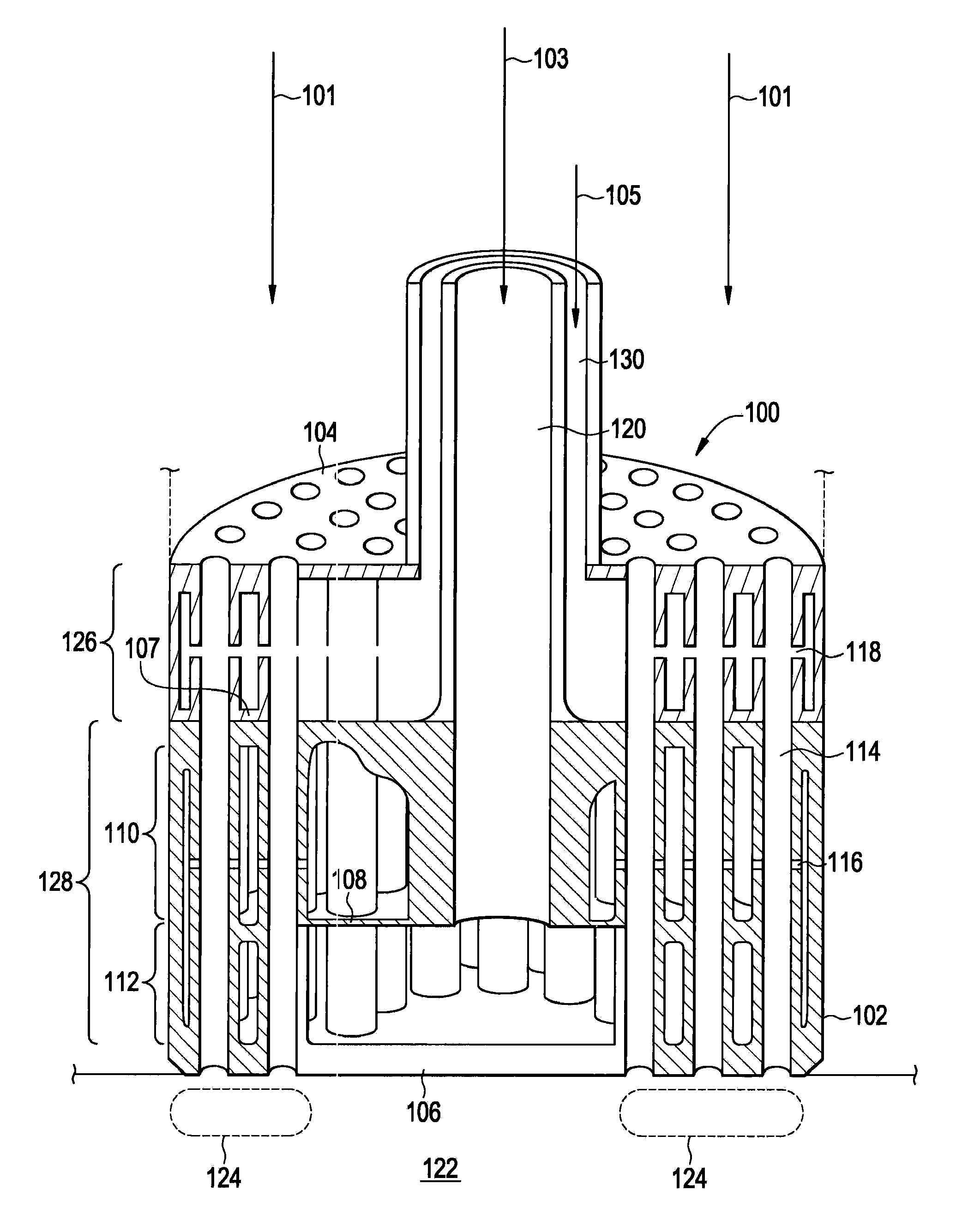
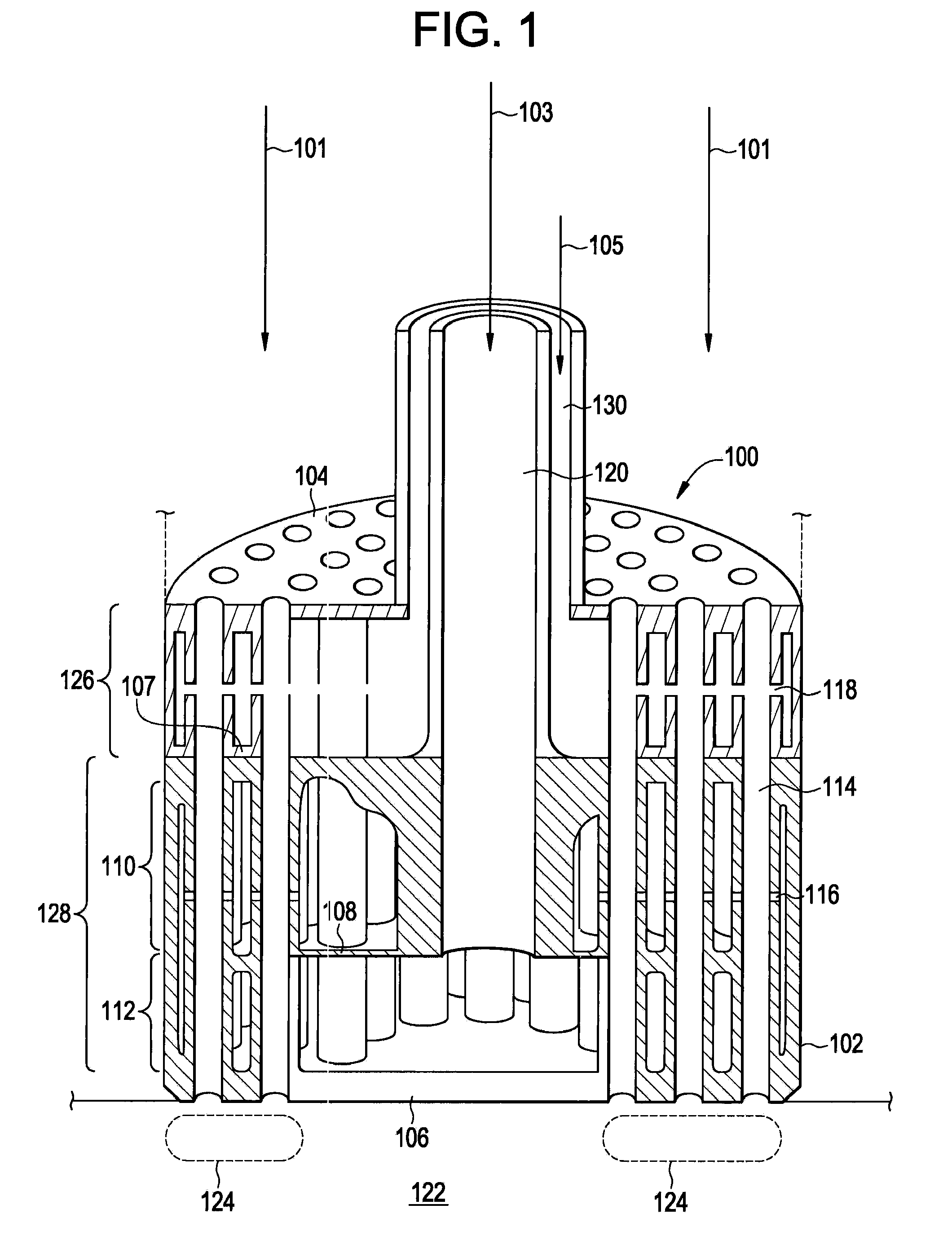
[0013]Gas turbine engines may operate using a variety of fuels. The use of natural gas (NG) and synthetic gas (Syngas), for example, offers savings in fuel cost and decreases carbon and other undesirable emissions. Some gas turbine engines inject the fuel into a combustor where the fuel mixes with an air stream and is ignited. One disadvantage of mixing the fuel and air in the combustor is that the mixture may not be uniformly mixed prior to combustion. The combustion of a non-uniform fuel air mixture may result in some portions of the mixture combusting at higher temperatures than other portions of the mixture. Locally-higher flame temperatures may drive higher emissions of undesirable pollutants such as NOx.

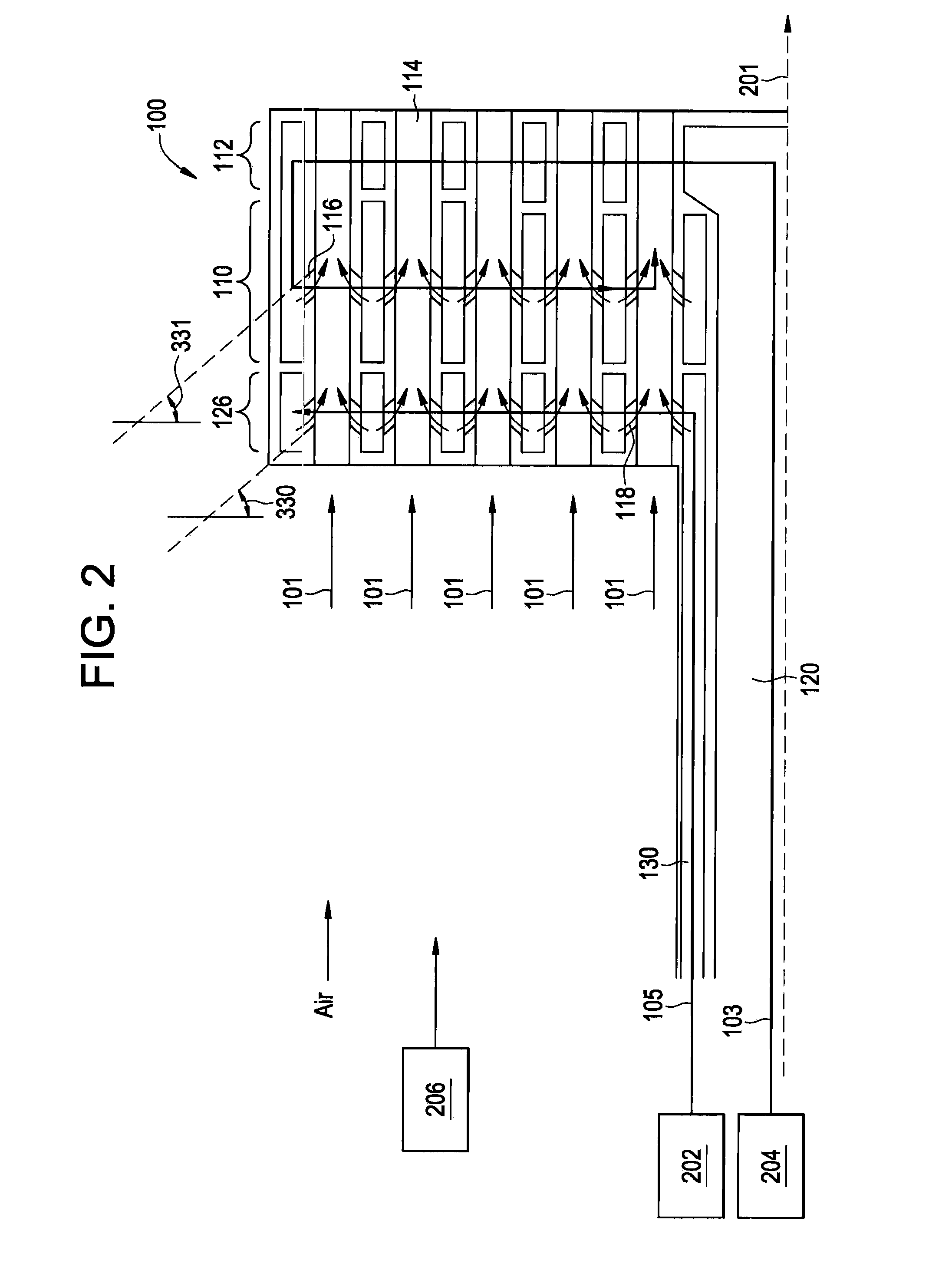
[0014]One method for overcoming the non-uniform fuel / air mixture in the combustor includes mixing the fuel and air prior to injecting the mixture into the combustor. The method is performed by, for example, a multi-tube fuel nozzle. The use of a multi-tube fuel nozzle to mix, f...


PUM


Abstract

A fuel injection nozzle includes a body member having an upstream wall opposing a downstream wall, and an internal wall disposed between the upstream wall and the downstream wall, a first chamber partially defined by the an inner surface of the upstream wall and a surface of the internal wall, a second chamber partially defined by an inner surface of the downstream wall and a surface of the internal wall a first gas inlet communicative with the first chamber operative to emit a first gas into the first chamber, a second gas inlet communicative with the second chamber operative to emit a second gas into the second chamber, and a plurality of mixing tubes, each of the mixing tubes having a tube inner surface, a tube outer surface, a first inlet communicative with an aperture in the upstream wall operative to receive a third gas.

Description

FEDERAL RESEARCH STATEMENT[0001]This invention was made with Government support under Government Contract #DE-FC26-05NT42643 awarded by Department of Energy. The Government has certain rights in this invention.BACKGROUND OF THE INVENTION[0002]The subject matter disclosed herein relates to fuel injectors for turbine engines.[0003]Gas turbine engines may operate using a number of different types of fuels, including natural gas and other hydrocarbon fuels. Other fuels, such as, for example hydrogen (H2) and mixtures of hydrogen and nitrogen may be burned in the gas turbine, and may offer reductions of emissions of carbon monoxide and carbon dioxide.[0004]Hydrogen fuels often have a higher reactivity than natural gas fuels, causing hydrogen fuel to combust more easily. Thus, fuel nozzles designed for use with natural gas fuels may not be fully compatible for use with fuels having a higher reactivity. At the same time, fuel nozzles designed for high-reactivity fuels may not be optimized ...

Claims


Application Information

Patent Timeline
Patent Type & Authority Applications(United States)
IPC IPC(8): F02C7/22
CPCF23D14/64F23R2900/00002F23R3/36F23R3/286
Inventor ZUO, BAIFANGKHAN, ABDUL RAFEYYORK, WILLIAM DAVIDZIMINSKY, WILLY STEVE
Owner GENERAL ELECTRIC CO
Why Eureka
Try Eureka