Device for Taking Samples from the Bottom Boundary Layer of a Water Body

a technology for water bodies and devices, applied in the field of oceanographic instruments, can solve the problems of inability to retard the descent of the device, the footings on the lower end of the support rods of the shock absorber unit, and the inability of instruments in use to sample the boundary layer in its original state, so as to ensure the vertical stability of the device, reduce the weight of the device, and reduce the effect of pressure on the contact surfa

Inactive Publication Date: 2011-04-14
DIMENTIO
View PDF15 Cites 16 Cited by
  • Summary
  • Abstract
  • Description
  • Claims
  • Application Information

AI Technical Summary

Benefits of technology

[0014]Since the suspended mud has thicker consistency than free water, the motion of the descending device may be retarded on the upper boundary of suspended mud if the contact surface is sufficiently large to enable it and/or the weight of the device is small, i.e. pressure on the contact surface is low. For this purpose, the footings on the lower end of the shock absorber units have been replaced by support belt f

Problems solved by technology

The instruments in use do not enable to sample the boundary layer in its original state in the bottom of a water body, because the penetration of the sampling tube into the sampling environment is accompanied by a smaller or greater shock.
Despite using the named above solutions, it is a drawback of such device when obtaining undisturbed samples that after a sample has been taken from the boundary layer the sectioning of the interior of the sampler's upper part (bathymeter) with valves helps to an extent avoid the mixing effect caused by oscillation and vibration due to waves and the flowing of the water (especially when the waves are high) when the device is lifted, but it has not been done in the lower part of the sampler that is foreseen for taking samples o

Method used


Image

  • Device for Taking Samples from the Bottom Boundary Layer of a Water Body
  • Device for Taking Samples from the Bottom Boundary Layer of a Water Body
  • Device for Taking Samples from the Bottom Boundary Layer of a Water Body

Examples


Embodiment Construction

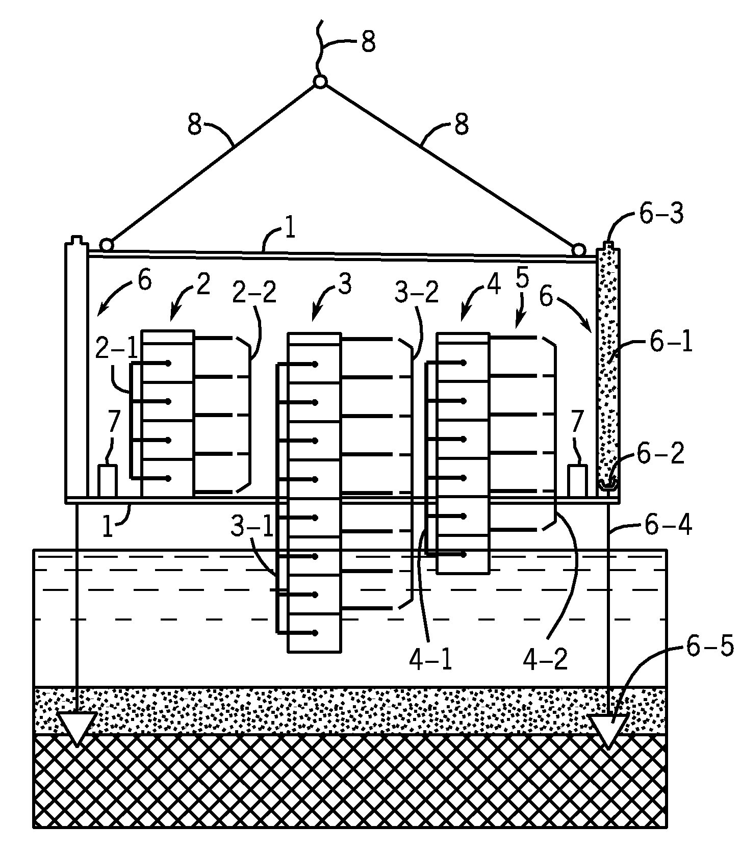
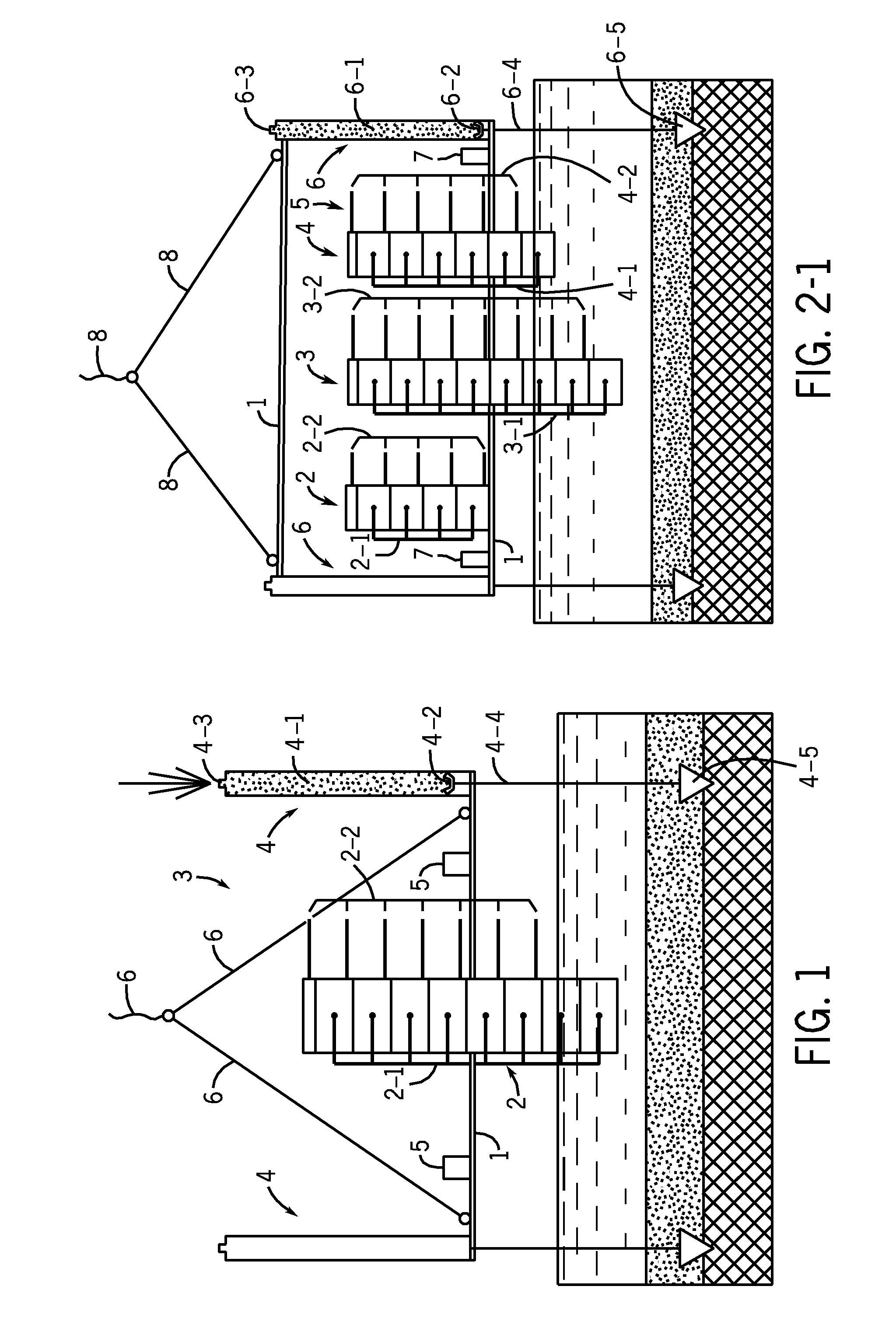
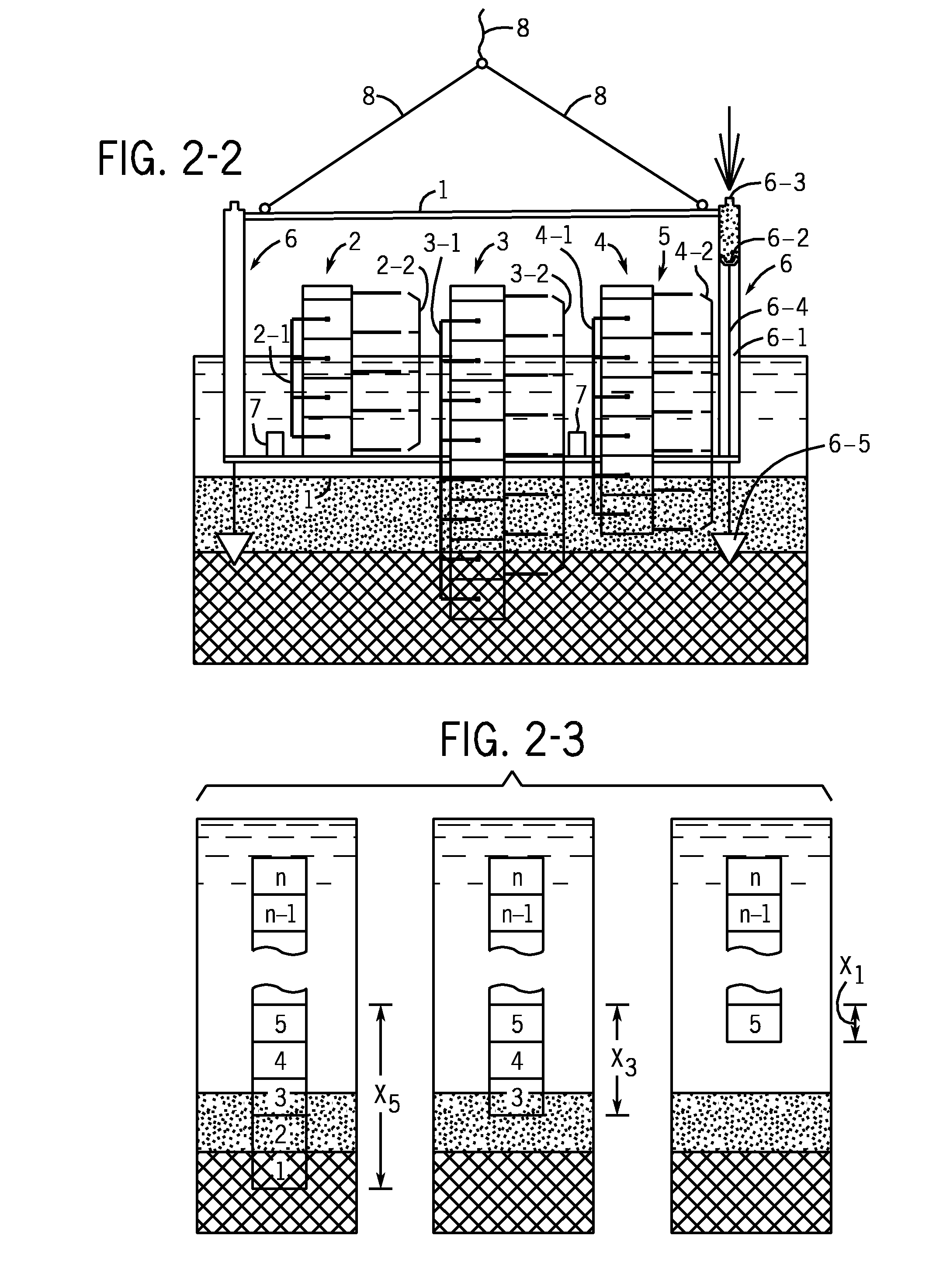
[0018]In FIG. 1-FIG. 3-3 the components comprised in the sampling device are marked with the following numbers and signs:

Name ofFIGS. 2-1 andFIGS. 1, 3-1, 3-2elementFIG. 12-2FIG. 2-3and 3-3Supporting 111frameSampling 22,3,42tubeSection2-12-1, 3-1, 4-12-1Horizontal 2-22-2, 3-2, 4-22-2valveControl unit353Shock 464absorber unitCylinder4-16-14-1Hydraulic 4-26-24-2plungerNozzle4-36-34-3Support rod4-46-44-4Footing4-56-5Support belt4-6Additional 57weightCable686Stabilizing 5balloonHigh-pressure 7gas balloonSamples 1, 2, 3, 4,from the 5, n-1, nbottomto the topThe routs of X1, X2sample and X3(5-th)movementWeight of the GdeviceBuoyancy of theH2stabilizing balloonBuoyancy of the H3supportbelt

[0019]FIG. 1 presents the known device for sampling in water basins.

[0020]FIG. 2-1 shows the presented sampling device, which differs from the sampler presented in FIG. 1 in that, several sampling tubes located at different heights are used.

[0021]FIG. 2-2 depicts the final moment of sampling with the devic...


PUM


Abstract

Devices using a winch are currently used for taking samples in the boundary layer formed at the bottom of a water basin.
In order to minimize the potential mixing effect at the whole length of the sampling tube, the design is presented where the sampling tube disassemble into sections is provided with horizontal valves dividing the interior of the tube into layers isolated from each other in the presented application, several shorter sampling tubes are used with their inlet holes being located at different heights. Thus, layers located at different heights are sampled by different sampling tubes. Substitution of contacts elements (shoes) with a contact surface, e.g. inflatable support belt, guarantees the stability of the sampling tube on the soft bottom. To ensure the vertical stability of the sampling tube, the device is provided with an upper stabilizing balloon. Regulating the buoyancy of the support belt and upper balloon by changing their filling degree, the device can be taken at regulated speed to the bottom of a water basin and lifted from the bottom to the surface without using any lifting cable.

Description

FIELD OF THE INVENTION[0001]The invention relates to the oceanographic instruments aimed at studying the structure and properties of elements in a water basin. More precisely, it belongs to the devices enabling to take non-mixed (undisturbed) samples from the boundary layer formed at the bottom of a water body. The boundary layer consists of compact bottom sediments, overlying suspended water-saturated mud layer, and near-bottom water layer directly connected with the latter.PRIOR ART[0002]The water body is characterized by the structure and concentration of elements in the boundary layer. The boundary layer formed at the bottom of a water body is labile in character (with an easily disturbable structure). It comprises much more substances and elements than can be found in the volume of the water body.[0003]The instruments in use do not enable to sample the boundary layer in its original state in the bottom of a water body, because the penetration of the sampling tube into the sampl...

Claims


Application Information

Patent Timeline
IPC IPC(8): G01N1/10
CPCG01N2001/1025G01N1/16
Inventor VOLL, MARTINERM, ANTSVOLL, ANDRESVOLL, MEHIS
Owner DIMENTIO
Why Eureka
Try Eureka