Tracheostomy tube having a cuffed inner cannula

Inactive Publication Date: 2011-04-14
VANDERBILT UNIV
View PDF24 Cites 46 Cited by
  • Summary
  • Abstract
  • Description
  • Claims
  • Application Information

AI Technical Summary

Problems solved by technology

There are many potential drawbacks with tracheostomy tubes which can range in effect from minor irritation to death.
Varying sizes of individuals and differences in anatomical dimensions leads to discomfort from tracheostomy tubes that fit poorly.
The rigid ends of the outer cannula often put pressure on the walls of the trachea, which can cause irritation, as well as ulceration.
When inflated, the friction

Method used


Image

  • Tracheostomy tube having a cuffed inner cannula
  • Tracheostomy tube having a cuffed inner cannula
  • Tracheostomy tube having a cuffed inner cannula

Examples


Embodiment Construction

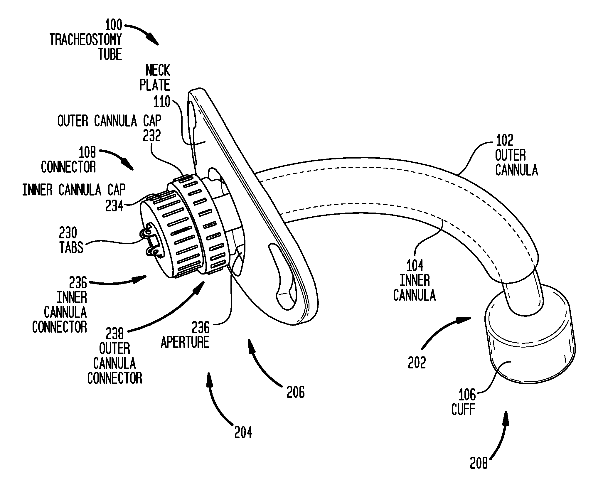
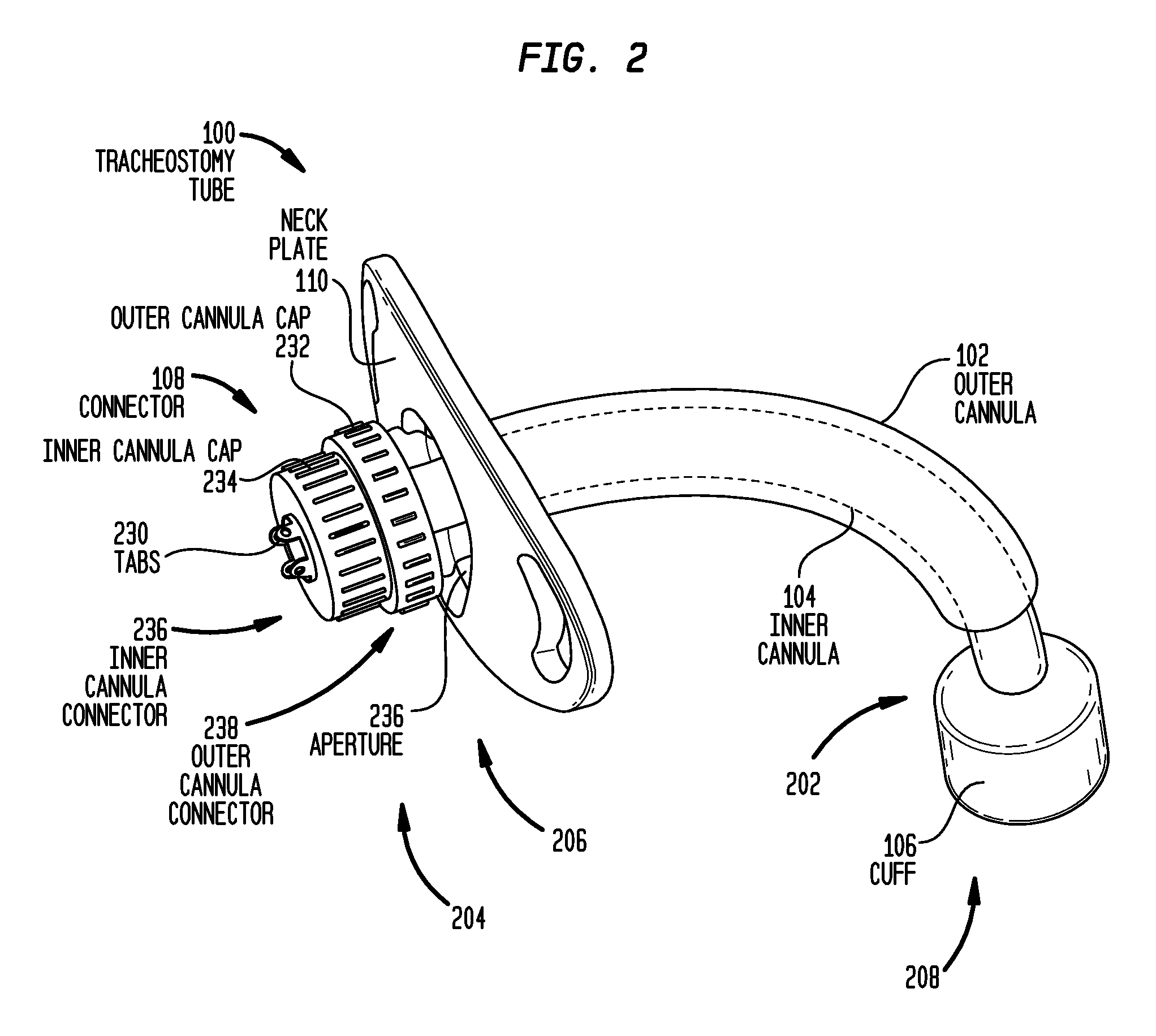
[0032]Embodiments of the present invention are generally directed to a tracheostomy tube usable with a neck plate having an aperture therein. The tracheostomy tube comprises an elongate outer cannula that is configured to extend through the neck plate aperture. An elongate inner cannula having an inflatable cuff is configured to extend through the lumen of the outer cannula such that the cuff extends beyond a distal end of the outer cannula. The tracheostomy tube further includes an interlocking mechanism configured to releasably secure a proximal end of the inner cannula to a proximal end of the outer cannula.

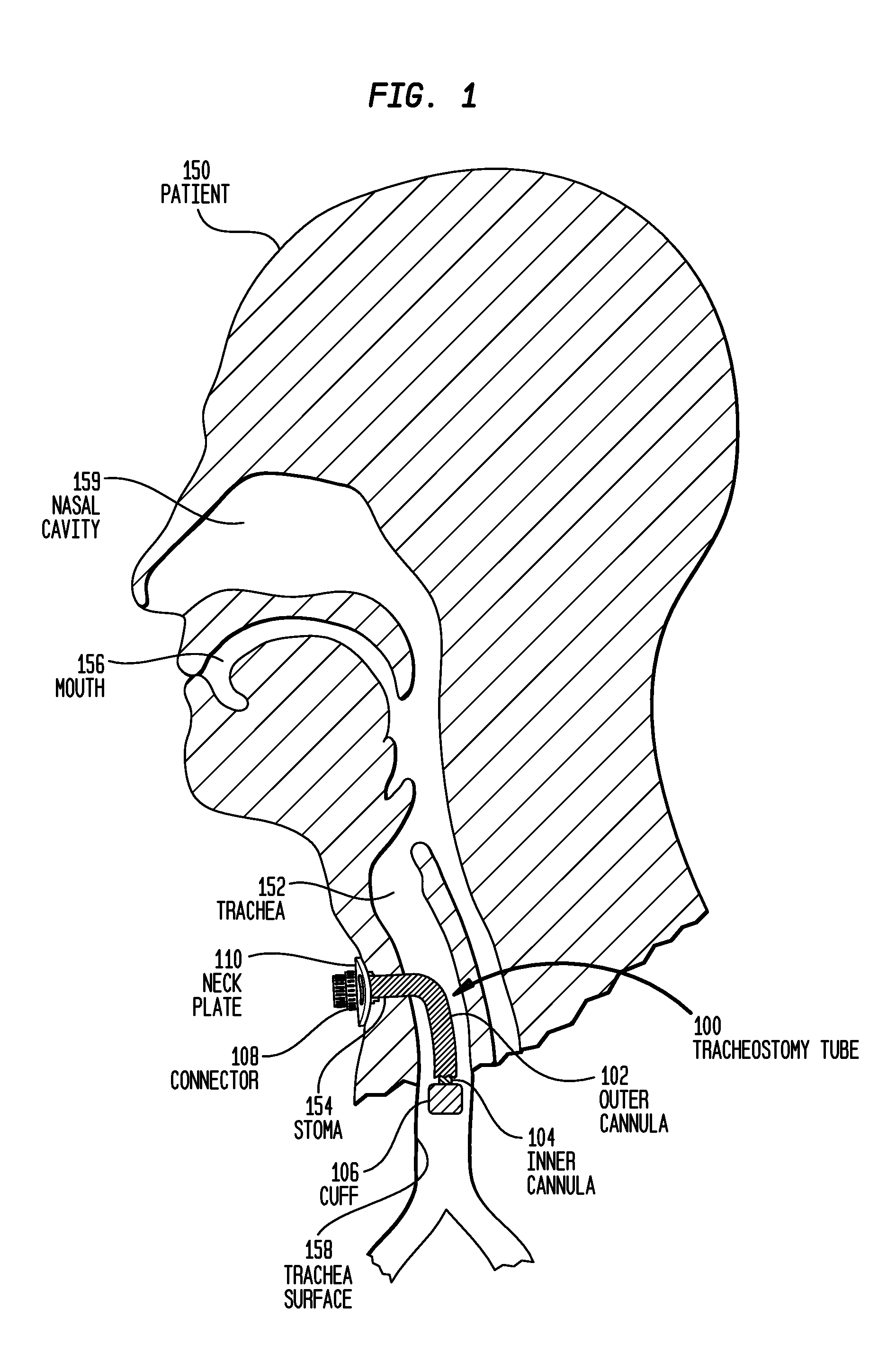
[0033]FIG. 1 is a cross-sectional view of a patient 150 illustrating an embodiment of a tracheostomy tube of the present invention, referred to herein as tracheostomy tube 100, inserted into trachea 152 of the patient. Tracheostomy tube 100 is used to maintain an airway when natural respiration is no longer possible. In one instance of use, tracheostomy tube 100 is required wh...


PUM


Abstract

A tracheostomy tube for use with a neck plate having an aperture. The tracheostomy tube comprises an elongate outer cannula having a lumen and configured to extend through the aperture; an elongate inner cannula having a lumen and an inflatable cuff, and configured to extend through the lumen of the outer cannula such that the cuff extends beyond a distal end of the outer cannula; and an interlocking mechanism configured to releasably secure a proximal end of the inner cannula to a proximal end of the outer cannula.

Description

CROSS-REFERENCE TO RELATED APPLICATION[0001]The present application claims the benefit of U.S. Provisional Patent Application No. 61 / 233,280 filed Aug. 12, 2009, which is hereby incorporated by reference herein.BACKGROUND[0002]1. Field of the Invention[0003]The present invention relates generally to tracheostomy tubes, and more particularly, to a tracheostomy tube having a cuffed inner cannula.[0004]2. Related Art[0005]Tracheostomy tubes are used to provide a direct airway to a patient's trachea when natural respiration is no longer possible. Tracheostomy tubes generally include an elongate cannula, catheter or other tube (generally and collectively referred to herein as “cannula”) formed so as to have a gradual curve to facilitate insertion into a patient's trachea. Typically, an incision commonly referred to as a stoma is made in the front of the patient's neck and trachea, below the patient's larynx and the cannula is inserted through the stoma. When it is located in its operativ...

Claims


Application Information

Patent Timeline
IPC IPC(8): A61M16/04
CPCA61M16/0434A61M16/0465A61M16/0427A61M16/0816A61M16/0488
Inventor WEBSTER, ROBERT J.DUTTON, TODDATHAVALE, SANJAY M.
Owner VANDERBILT UNIV
Why Eureka
Try Eureka